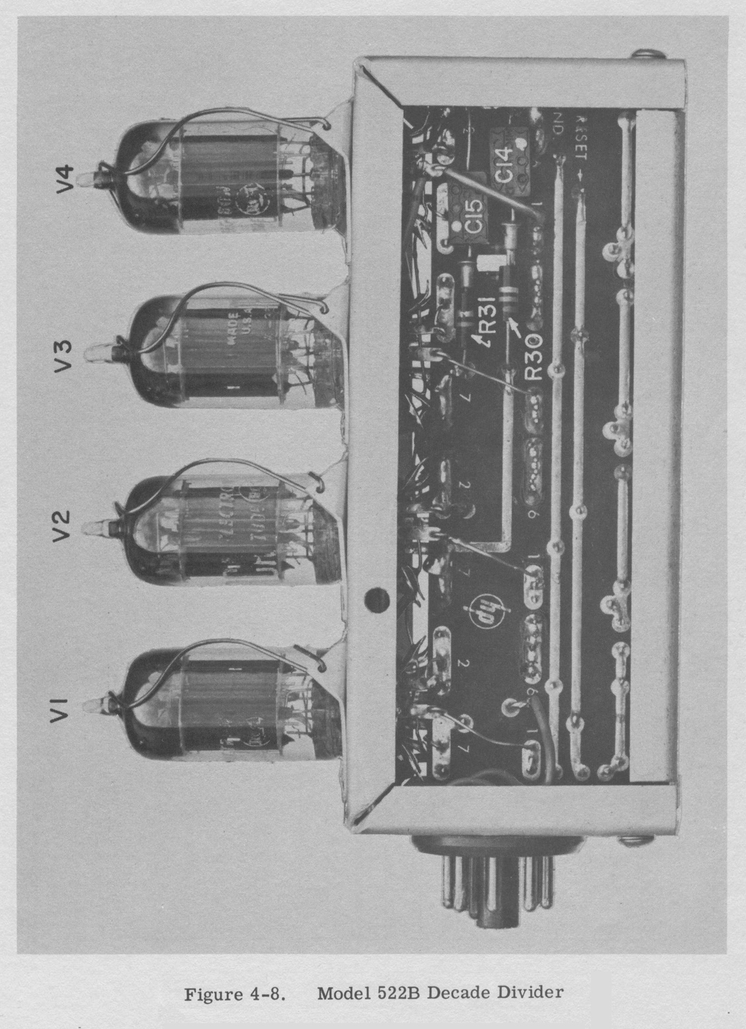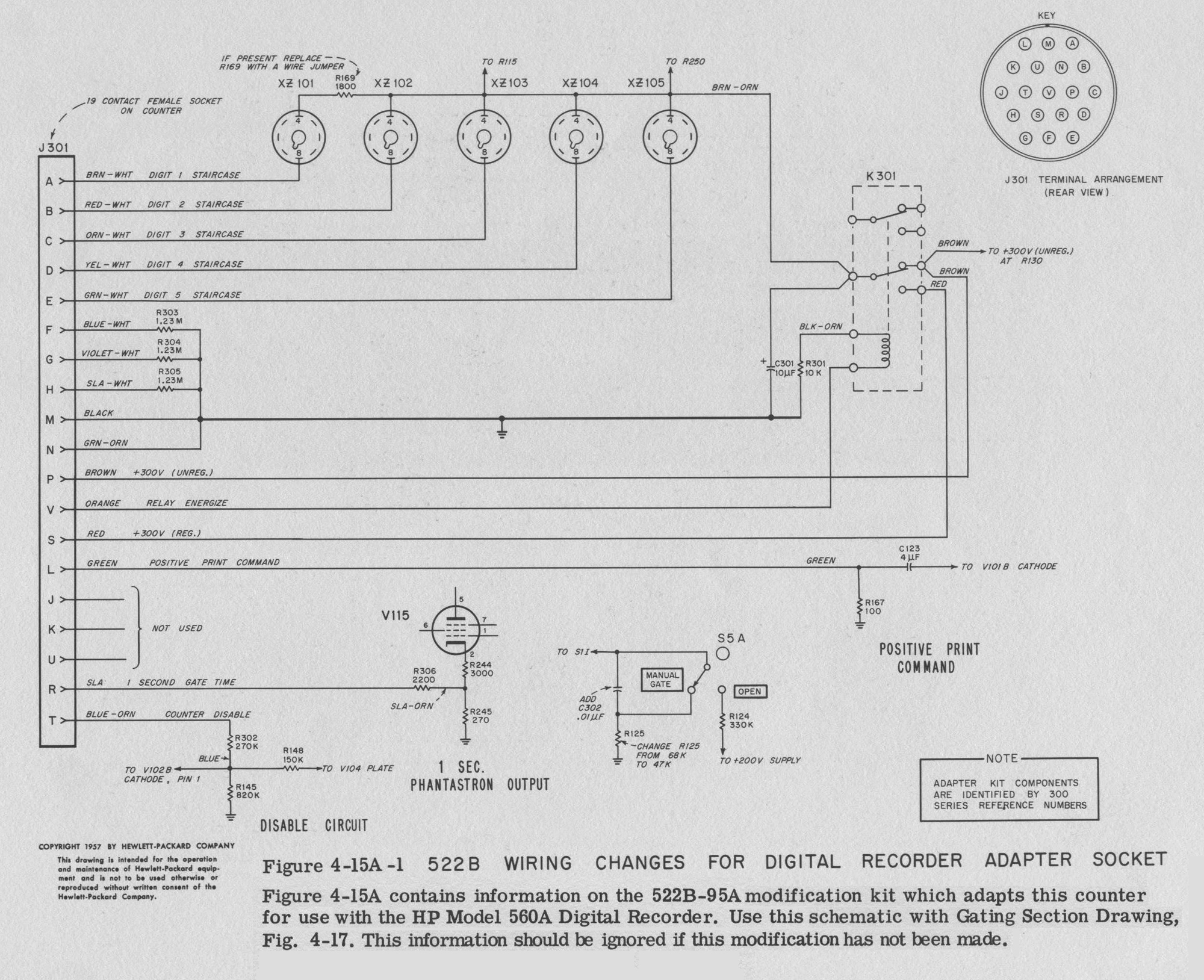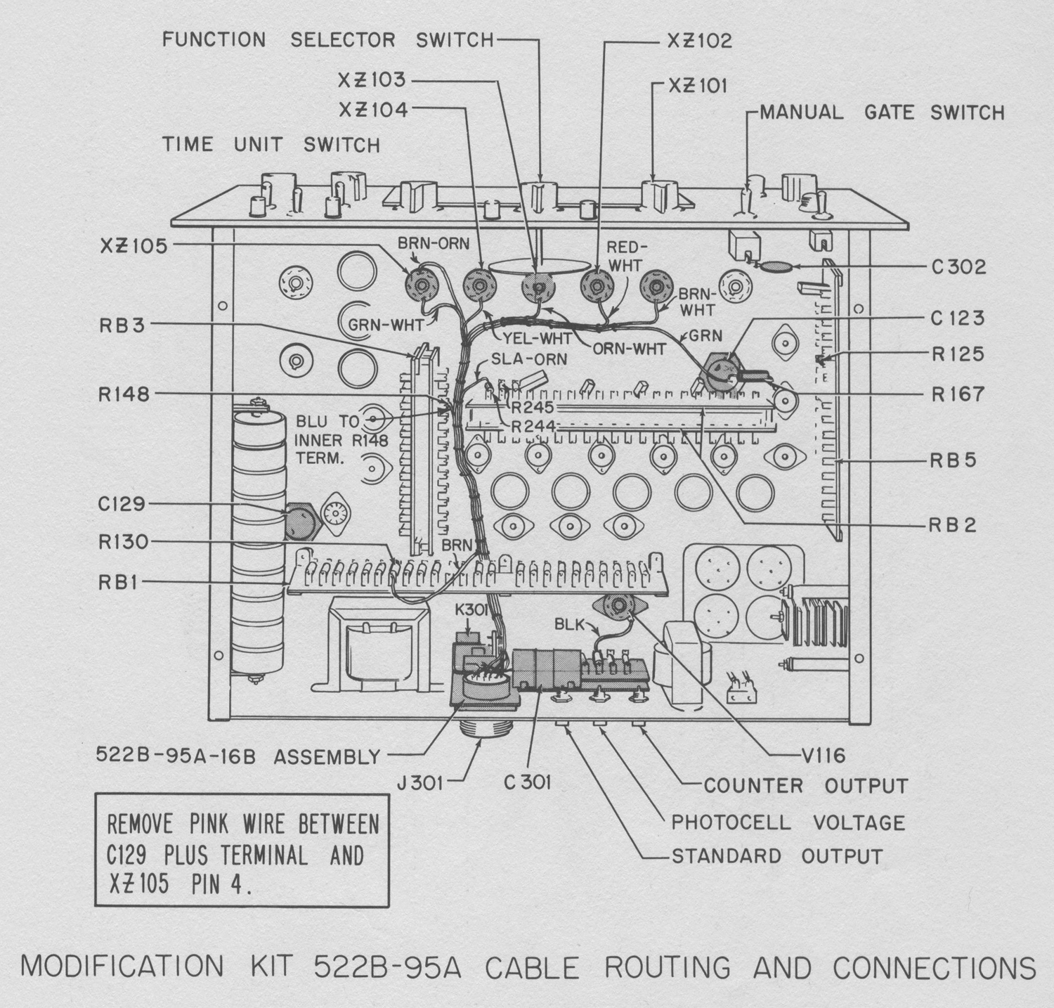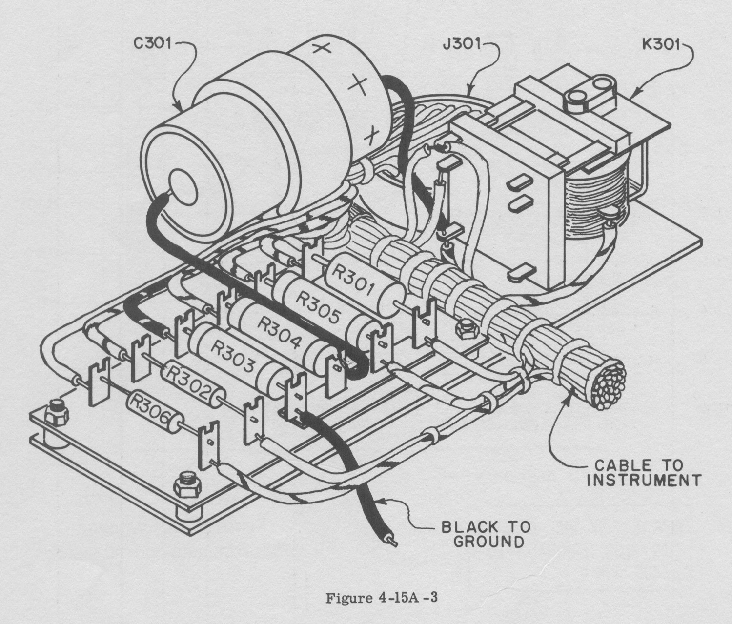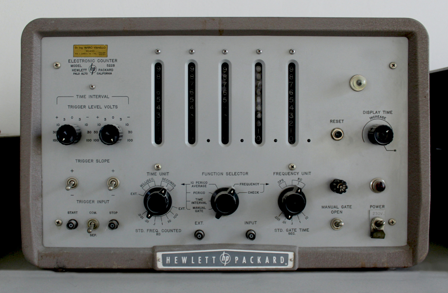
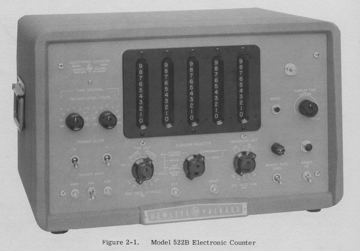
Electronic Counter Hewlett-Packard Model 522B 1ª parte

Electronic Counter  Hewlett-Packard Model 522B Serial 2733, Palo Alto California.
Importato da: Dott. Ing. Mario Vianello – Milano.  Prima parte.

Nell’inventario D del 1956, in data 7 giugno 1960, al n° 1800 si legge: “Fondazione Carlo e Giuseppe Piaggio – Genova.  Contatore elettronico HP mod. 522. Destinazione Radiotecnica”.
All’indirizzo:
https://www.hpl.hp.com/hpjournal/pdfs/IssuePDFs/1952-11.pdf

si può trovare l’ Hewlett-Packard Journal Vol. 4 No. 3  del novembre 1952.
Il cui titolo è: “A New 100 KC Counter for Use in Electronics and Industry”.
Noi  abbiamo preferito riportare una parte del manuale di istruzioni poiché le figure, opportunamente elaborate, sono meglio definite.
Abbiamo diviso il testo in due parti a causa della sua lunghezza e del numero di foto e figure.
Abbiamo deciso inoltre di omettere il capitolo “Maintenance”, ma ne abbiamo riportato le figure.
§§§
«SPECIFICATIONS
Measures:
Frequency
Period
Time interval
Ratio
Total Events
Registration:   Five places. Output pulse available to actuate trigger circuit for mechanical register providing increased count capacity.
Stability:    Within 10 parts per million per week. Can be standardized with standard frequency transmission from WWV.
Answer Display Time: Variable from 0. 1 to 10 seconds. Display can be held indefinitely if desired.
Check:  Panel control provides automatic count of 100 kc to assure accuracy of gate and proper operation of counters.

FREQUEN CY MEASUREMENT
Range:   10 cycles/sec. 120 kc. Extendable to 220 kc by replacing units AC-4A DECADE with an hp Model AC-4B DECADE.
Accuracy:    ±1 count, ± stability (see above).
Input Sensitivity:   . 2 volt rms minimum. Direct coupled input. (. 5 volt rms required with AC-4B above 120 kc.)
Input Impedance: Approximately 1 megohm shunted by 50 μμf.
Gate Time: 0.001, 0.01, 0.1, 1. 0 and 10 seconds. May be extended to any multiple of l or 10 seconds by manual gate toggle switch. Panel neon lamp indicates when gate is open.
Reads In: Cps or kc. Lighted decimal point automatically positioned.

PERIOD MEASUREMENT
Range:  .00001 cps to 10 kc. Output pulse is available to actuate trigger circuit for mechanical register to extend range to lower frequency.
Accuracy:  ± count, ± 3%, ±stability (see Frequency Measurement) for  measurement of one period. Accuracy for more than one period is  ± 3% divided by number of periods ± stability. (This applies to a1 volt rms input signal. Accuracy increases with greater input signal levels.)
Input Requirements: . 2 volt rms minimum. Direct coupled input.
Input Impedance: Approximately 1 megaohm shunted by 50 μμf.
Measurement Period: One or ten cycles of unknown frequency. May be extended to any number of cycles of unknown frequency by manual control. This is limited to frequencies below 50 or 60 cycles/sec.
Standard Frequency Counted: 1, 10, 100 cps; 1, 10, 100 kc. External frequencies can also be used.
Reads In: Seconds or milliseconds. Lighted decimal point automatically positioned.

TIME INTERVAL MEASUREMENT
Range: 10 microseconds to 100, 000 seconds (27. 8 hrs.)
Accuracy: ± 1/std. frequency, ± stability (see Frequency Measurement.)
Input Impedance: Approximately 250, 000 ohms shunted by 50 μμf.
Input Requirements: 1 volt peak minimum. Direct coupled input.
Start and Stop Inputs: Independent or common channels.
Trigger Slope: Positive or negative on either channel.
Trigger Amplitude: Continuously adjustable on both channels from -100 to +100 volts .
Standard Frequency Counted: 1, 10, 100 cps; 1, 10, 100 kc. External frequencies can also be used.
Reads In: Seconds or milliseconds. Lighted decimal point automatically positioned.

GENERAL
Power Supply: 115/230 volt, 50-60 cps, 260 watts.
Size: Cabinet Mount: 20-3/4 i.nch wide, 12-1/2 inch high, 14-1/2 inch deep.
Rack Mount: 19 inch wide, 10-1/2 inch high, 14-1/2 inch deep.
Weight: Cabinet Mount: 45 lbs.; approx. shipping weight, 90 lbs.
Rack Mount: 40 lbs.; approx. shipping weight, 80 lbs.
Features:
a) Operates with -hp— 508 Tachometer Generators for tachometry.
b) Operates with -hp— 520A for high speed nuclear scaling, or directly for peak rates up to 100, 000 per second.
c) Measures frequency ratios.
d) Operates as electronic stop watch with manual start, stop and reset.
e) Operates as a secondary frequency standard providing precise rectangular output voltages at 1, 10, 100 cps; 1 and 10 kc and a 100 kc sine wave. Amplitude, approximately 1 volt peak.
Accessories Provided: 2 – AC-16D cable assemblies, 44 inches RG-58/U terminated one end with UG-88/U Type BNC connector.
Accessories Available: AC-4B Decade Divider Unit which increases top frequency range to 220 kc.
AC -16K Cable Assembly, 48 inches RG-58/U terminated both ends with UG-88/U Type BNC connectors.
AC-17 End Frames with handles for bench use of rack mount unit. -hp- Model 508 Tachometer Generators. Convert -hp- Model 522B into tachometer indicator with direct mechanical connection to equipment under test.
SECTION I

GENERAL DESCRIPTION

1.1 INTRODUCTION
The Model 522B Electronic Counter is an accurate and easy to use instrument for frequency, period, and time interval measurements. Frequency measurements from 10 cycles/sec. to 120 kc* and period measurements from .00001 cycles/sec. to 10 kc may be made with this instrument. The instrument and display of the counted value may be preselected for automatic operation or set to any desired interval by manual control. This counter is suitable for standard audio-frequency oscillators to very high accuracy and facilitates  response measurements of sharply resonant networks. The frequency stability of oscillators as a function of time may be measured directly with this instrument. Transducers which provide an output frequency related to the magnitude of such physical constants as
___________________________________________
* The 522B can be quickly and easily converted to measure frequencies as high as 220 kc by simply replacing the “UNITS” AC-4A Decade Counter unit with an -hp- Model AC-4B Decade Counter unit. The decade units plug in and no special adjustments need be made. weight, pressure, temperature, small distances and force may be used with the electronic counter for increased accuracy and quickness of reading. Exceptionally accurate tachometer measurements are obtained by connecting a transducer, which translates rotation into electrical impulses, to the input of the counter.
1-2 INSPECTION   [Omissis]
SECTION II

OPERATING INSTRUCTIONS

2-1 CONTROLS AND TERMINALS
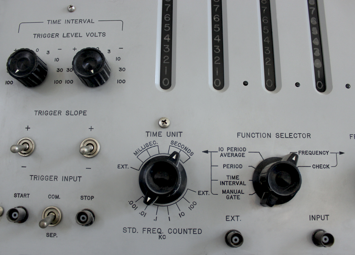
CONNECTORS
All cable receptacles on the instrument are BNC type UG-625A/U. Connector UG-88/U Should be used with these receptacles.
TIME INTERVAL
The designations and functions of the various controls and terminals that comprise the time interval section of the instrument are listed below.
TRIGGER INPUT
START – This connector is the input terminal for the start channel during TIME INTERVAL measurement. The TRIGGER SLOPE switch and TRIGGER LEVEL VOLTS control above the connector are part of the START input circuit
STOP – This connector is the input terminal for the stop channel during TIME INTERVAL measurement. The TRIGGER SLOPE switch and TRIGGER LEVEL VOLTS control above the connector are part of the STOP input circuit.
COMM. -SEP. – The START and STOP connectors are connected together when this toggle switch is in the COM. (common) position. Under this condition both the start and stop trigger voltage may be applied to the-instrument through either the START or STOP connectors. In the SEP. (separate) switch position there is no connection between the START and STOP connectors and the start and stop trigger voltages must be applied to their respective connectors.
TRIGGER SLOPE
In the positive position of the switches, the rising portion of the wave controls the time interval. In the negative position the falling portion of the wave controls the time interval. The left hand switch is for the start channel. The right hand switch is for the stop channel.
TRIGGER LEVEL VOLTS
These controls establish the triggering level of the start and stop channels.
TIME UNIT
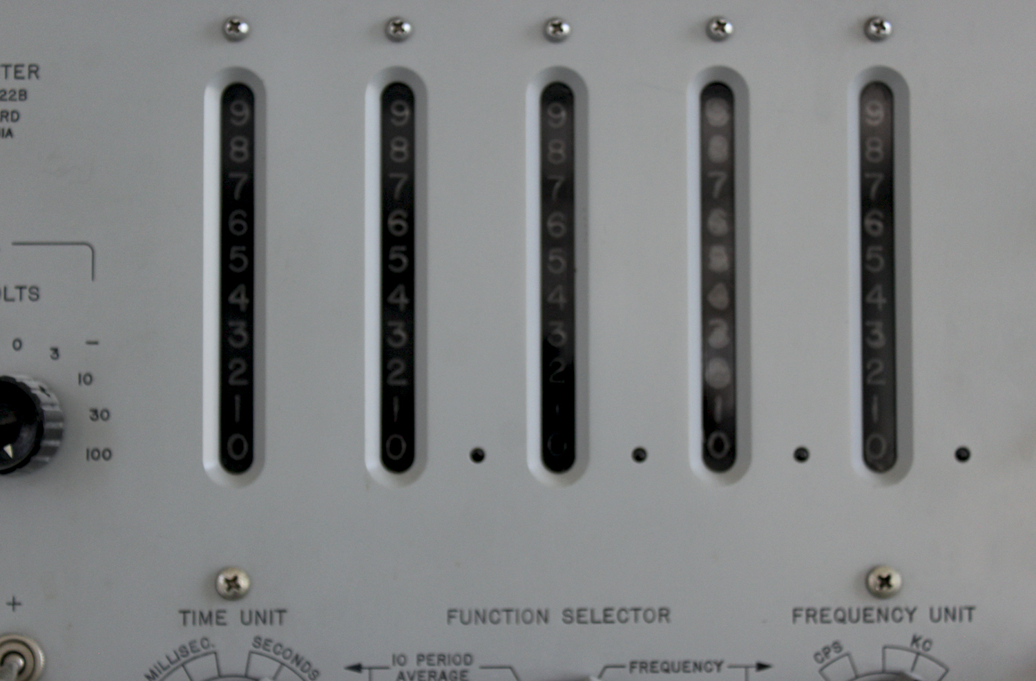
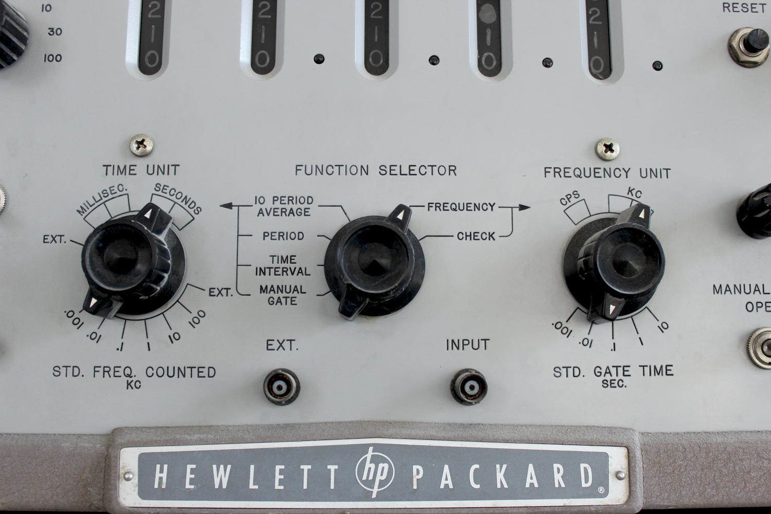
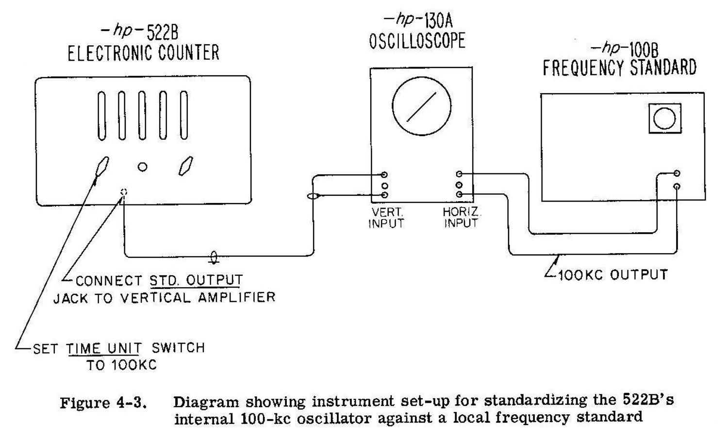
The TIME UNIT switch selects the units of time for the time measurements shown on the left side of the FUNCTION SELECTOR switch (10 PERIOD AVERAGE to MANUAL GATE). Indications are in seconds or milliseconds with decimal point indicated. The designations below the switch are the counted frequencies, in kilocycles, obtainable from the standard time base. The switch position designated EXT. is for an externally counted frequency. In this position the EXT. connector is substituted in place of the internal standard time base. No time unit is specified when the EXT. position is used and no decimal point appears.
FUNCTION SELECTOR
This switch sets up the various circuits to perform the functions shown by the switch position designations. The designations on the left side of the FUNCTION SELECTOR switch pertain to time measurements while those on the right side are for frequency measurements. The switch position designations and their functions are as follows:
10 PERIOD AVERAGE – Measures the incoming waveform for a period of ten cycles and displays the period of one cycle. The units of measurement of time are dependent on the setting of the TIME UNIT switch.
PERIOD – Measures the incoming waveform for a period of one cycle and displays this period. The units of measurement of time are dependent on the setting of the TIME UNIT switch.
TIME INTERVAL – Measures and displays the time interval between the start and stop trigger voltages. The units of measurement of the time interval, are dependent on the setting of the TIME UNIT switch.
MANUAL GATE – This function is used for long-term counting where the gate is controlled by means of the MANUAL GATE switch. In this position the instrument may be used as an electronic stop watch.
FREQUENCY – Counts and displays frequency of incoming waveforms. Counting time depends on the setting of the FREQUENCY UNIT switch.
CHECK – The instrument is self-checking when the switch is in the CHECK position.
FREQUENCY UNIT
This switch determines the length of time in seconds that the gate is open during frequency measurements. The frequency units are indicated above the knob.
DISPLAY TIME
This control varies the time that the count is displayed. The minimum display time obtainable is .1 second or the gate time, whichever is larger. The maximum time is 10 seconds unless the control is switched to ∞ in which case the count  is displayed indefinitely. When the control is in  the ∞ position, the count is displayed until the counting cycle is started again by depressing the RESET button.
RESET
When this button is depressed, the counters are returned to zero and a new counting cycle is ready to start.
FUSE
The fuseholder, located on the control panel, contains a 3.2 ampere cartridge fuse. For 230 volt operation the fuse should have a rating of 1.6 amperes. Replacement fuses must be of the “Slo-Blo” type as specified in the Table of Replaceable Parts in this instruction manual.
POWER ON
This switch controls all the power supplied to the instrument.
MANUAL GATE
This switch opens and closes the gate when the FUNCTION SELECTOR switch is in the MANUAL GATE position. In other positions of the function switch, the MANUAL GATE switch in the OPEN position prevents the stop pulse from closing the gate.
INPUT
This connector is the input terminal for frequency and period measurements. During TIME INTERVAL, MANUAL GATE, and CHECK functions this connector is grounded through the input coupling network.
EXT.
This connector is the input terminal for any external time unit and is connected in place of the internal time unit when the TIME UNIT switch is in the EXT. position.
POWER CABLE
The three-conductor power cable on the 522B is terminated in a polarized three-prong male connector recommended by the National Electric Manufacturers’ Association. The third contact is an offset round pin, added to a standard two-blade a-c plug, which grounds the instrument chassis when used with the appropriate receptacle. To use this NEMA plug in a standard two-contact outlet, it is recommended that instead of breaking off the ground terminal, a 2-prong to 3-prong adapter be used. The ground connection emerges from the adapter as a short lead which should be connected to ground for the protection of operating personnel.
COUNTER OUTPUT
The output of the last counter is available at this terminal, located on the back of the chassis.
PHOTOTUBE VOLTAGE
A +90 volt polarizing voltage is available at the rear of the instrument. It has an internal impedance of approximately 100,000 ohms.
STD. OUTPUT
Internally-generated standard frequencies are available  at this connector. These frequencies are the STD. FREQUENCY COUNTED and are selected by means of the TIME UNIT switch.2-2 OPERATION
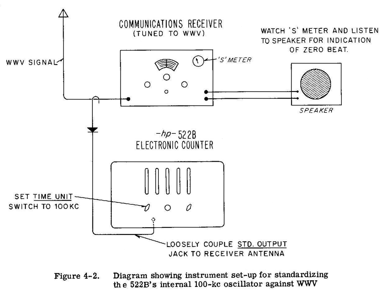
It should be kept in mind while using the Model 522B that this instrument measures, basically, frequency or time. There are two basic time measurements that can be performed, period and time interval. Period measures the time between two consecutive points on a single waveform. Time interval measures the time between two separate waveforms. This instrument requires a warm-up period of at least 30 minutes before the specified accuracy is obtained from the crystal. Less accurate measurements may be made after a 30 second warm-up, and the sensitivity will be approximately 1/2 volt at this time. Before making any measurements with this instrument, it is desirable to check the performance of the instrument by means of the built-in checking circuit. This is done as follows:
a. Set the FUNCTION SELECTOR switch to the CHECK position and the FREQUENCY UNIT switch to 1 SEC.
b. Set the DISPLAY TIME control fully counter-clockwise.
c. If all the counters display zero at the end of the count, then the instrument is performing  properly. If this count is not displayed, refer to the  Maintenance section for probable causes and remedies.
The procedure for operating, the Model 522B is as follows:

NOTE: The input circuit of the 522B is direct coupled to the amplitude discriminator. Any dc voltage present at the input will affect the sensitivity of the amplitude discriminator circuit when measuring FREQUENCY or PERIOD. If dc voltage is present, an external 2 μf blocking capacitor connected in series with the INPUT jack will allow measurements to be made down to 1 cps at rated sensitivity. A larger capacitor is required for lower frequencies.
Frequency Measurement
a. Set the FUNCTION SELECTOR switch to FREQUENCY and the FREQUENCY UNIT switch to the STD. GATE TIME position that provides the desired measuring unit. MANUAL GATE switch in the closed position.
b. Connect the unknown frequency to the INPUT connector of the instrument. The input voltage must not exceed 100 volts. As this instrument is triggered whenever the input voltage passes through zero, any direct current component in the input voltage will change the triggering point.
For example, an input voltage of 5 volts which has a direct current component of 10 volts will not trigger the instrument. However, an input voltage of 15 volts with a 10 volt direct current component will trigger the instrument at the 10 volt level.
c. The MANUAL GATE switch may be used to extend the time that the gate is open so that multiples of  the selected gate time may be obtained. When the MANUAL GATE switch is in the OPEN position the gate cannot close. When the switch is returned to the closed position, the gate will close at the next timing pulse. To extend the gate time, the MANUAL GATE switch is placed in the OPEN position. Just prior to the desired count time the MANUAL GATE switch should be returned to normal, and the next timing pulse will accurately close the gate.
Example: It is desired to measure a 5000 cycle/sec. wave for a time of 4 seconds. The time unit selected on the FREQUENCY UNIT switch would be 1 second. The MANUAL GATE switch may be open either before or after the count has begun but must be open before 1 second of counting time has elapsed. It must be closed between the 3rd and 4th second of counting time.
d. Adjust the DISPLAY TIME control so that the count is displayed long enough to be read conveniently. The count display will be cycles or kilocycles per second as indicated by the position of the FREQUENCY UNIT switch.
10 Period Average Measurement
a. Set the FUNCTION SELECTOR switch to the 10 PERIOD AVERAGE position and the TIME UNIT switch for the desired unit time. Connect the  waveform to be measured to the INPUT terminal. The direct current component of the input waveform must be considered as it will produce the effects described in the Frequency Measurement procedure. The MANUAL GATE switch should-be in the closed position.
b. Adjust the DISPLAY TIME control for convenient reading of the count. The displayed count will be the average period of one cycle although 10 cycles were measured. The MANUAL GATE switch will function on period measurements similar to frequency measurement. However, on period measurements the time is a multiple of the input wave, for example: It is desired to measure the period of a 20 cycles/ sec. wave for 100 periods. On 10 period average the count displayed will be 50.0 milliseconds. Then for 100 periods which is 10 times 10 period average, the count should be 500.0 milliseconds. Thus the MANUAL GATE switch should be closed between the 9th and 10th ten periods which would be between 450.0 and 500.0 count. The period of the 20 cycles/sec. wave will now be 500.0 divided by 10 or 50.00 milliseconds. The accuracy has been increased by ten time over the accuracy of the ten period average.
Period Measurement
The procedure for measuring the period of one cycle is the same as for the 10 Period Average except that the FUNCTION SELECTOR switch is set at PERIOD.
Time Interval Measurement
a. Set the FUNCTION SELECTOR switch at TIME INTERVAL and the TIME UNIT switch at the desired time unit. The MANUAL GATE control must be in the closed position.
b. If the interval of time to be measured is a pulse-width, repetition rate, rise time of a sloping wave, or some other function in which both start and stop information is on a single wire, set the SEP. -COM. switch to COM. and connect the input voltage to either the START or STOP terminal. In the COM. position the two inputs are tied together. If the interval to be measured is from two separate sources – such as two phototube or two sine waves of different phase – place the SEP. -COM. switch in SEP. Connect the starting signal to the START terminal and the stop signal to the STOP terminal.
c. The TRIGGER SLOPE switches and TRIGGER LEVEL VOLTS controls are the same for both the start and stop channels. The following  considerations therefore apply to both channels.
If the desired trigger point of the input waveform is rising (going in a positive direction), set the TRIGGER SLOPE switch to +. If the desired trigger point of the input waveform is falling (negative going), the TRIGGER SLOPE should be set to -.
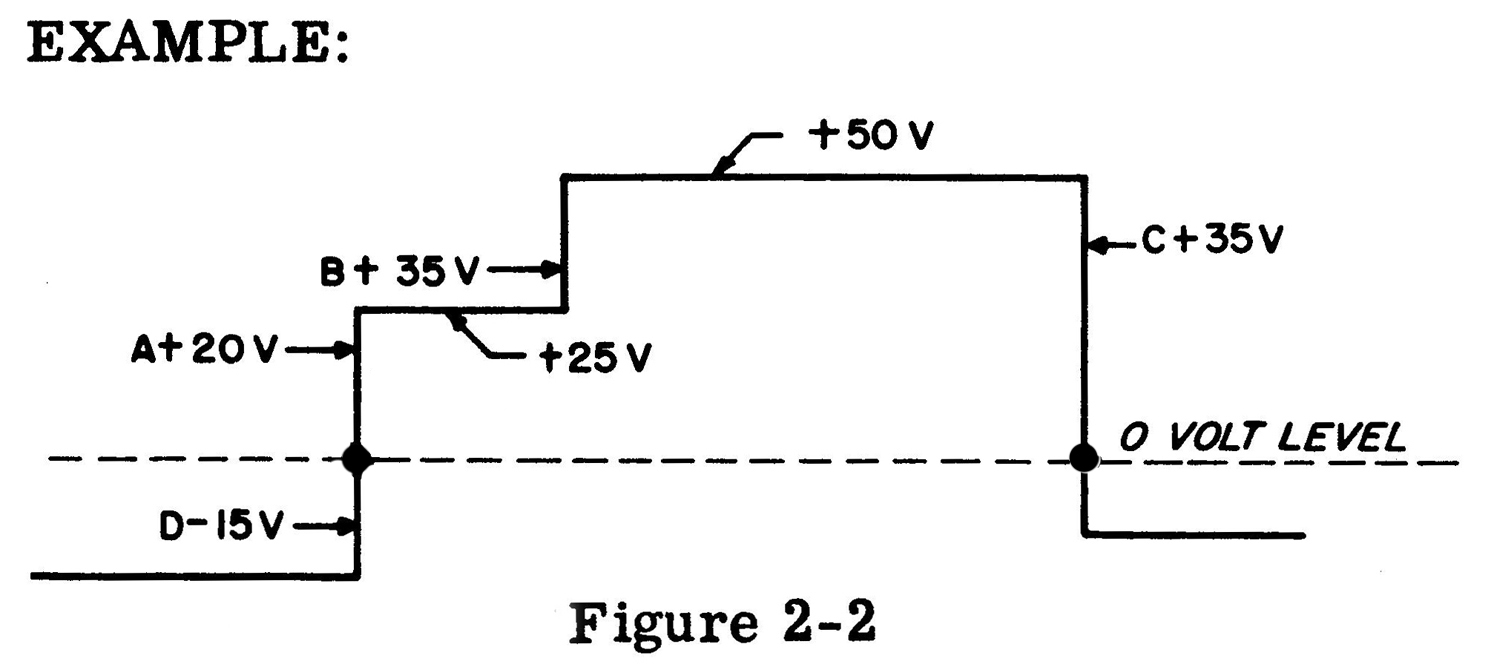
To set the TRIGGER LEVEL VOLTS controls it is necessary to know the voltage levels of the input wave. The TRIGGER LEVEL VOLTS control is then set to the voltage value desired. Any direct current component of the signal must also be considered when setting these controls.It is desired to measure the time between points A and C of Figure 2-2. Since this is a single signal, the SEP. -COM. switch should be in the COM. position. Since the voltage at point A is rising, set the start TRIGGER SLOPE switch to +. and the start TRIGGER LEVEL VOLTS control to +20. Point C is negative going and the stop TRIGGER SLOPE switch should be set to -. The stop TRIGGER LEVEL VOLTS should be set to +3 5V. Set the TIME UNIT switch to the desired unit. It will be noted that if the start TRIGGER LEVEL VOLTS control were set to +35 instead of +20, the time from points B to C would be measured. Also if the stop TRIGGER SLOPE switch were changed to + instead of -, the time between points A and B would be measured. In measuring the time between A and C the start TRIGGER LEVEL VOLTS control could be set at point D (-15V) which will give the same time.
External Input
In both period and time interval measurements, it may be desirable to have a count in some unit other than or in terms of some other frequency. For instance, the period of a 2 cycle wave could be in terms of some other wave, say 3600 cycles. This gives the ratio of the two frequencies which would be 1800 to 1. The procedure for using the external input is as follows:
a.Set the FUNCTION SELECTOR switch to the 10 PERIOD AVERAGE, PERIOD, or TIME INTERVAL position.
b. Set the TIME UNIT switch to EXT. and connect the external frequency to the EXT. terminal.
c. Connect the source to be measured to the INPUT terminal or the START and STOP terminals (Time Interval) whichever function is being used.
d. The displayed count is obtained in units of the external signal applied to the instrument. When the TIME UNIT switch is in the EXT. position, the decimal points are not illuminated.
Manual Gate
a. Set the FUNCTION SELECTOR switch to MANUAL GATE and the TIME UNIT switch to the EXT. position.
b. Set the MANUAL GATE switch to the closed position. Connect the source to be measured to the EXT. terminal.
c. To start the count, throw the switch to the OPEN position. At the end of the desired elapsed time change the switch back to the closed position. Read the displayed count, push the RESET button and the instrument is ready to count again. The time, during which the gate is open, must be measured by some device outside of the instrument.
In this operation the MANUAL GATE switch actually opens and closes the gate at the instant the switch is operated and not at the next timing pulse as in all of the previous operations. The MANUAL GATE switch may be opened and closed as often as desired and no resetting will occur. Resetting must be done manually by the RESET button, and may be done at any time.
2-3 ACCURACY
Frequency Measurements
The basic counter accuracy is determined by two factors. One factor is the stability of the 100 kc crystal  standard in the time base, which is 10 parts per million or .001 percent per week. A second factor is the inherent error of ±1 count present in all counters  of this type. This error is due to phasing between the timing pulse that operates the electronic gate and the pulses that pass through the gate to the counters. The chart in Figure 2-3 shows the errors to be expected for frequency or period measurements. For example, if a frequency of 10 kc is being measured with a 10 second gate time, there will be a total of 100,000 counts. An error of +1 count is .001 percent accuracy. If 20 kc is measured for 10 seconds, a total of 200,000 counts, ±1 count is .0005 percent. However, the accuracy (.001 percent) of the crystal standard also must be taken into consideration. The overall accuracy for frequency measurements then is as follows:
Maximum Possible error (percent) = ± 1 count  ± accuracy of standard.
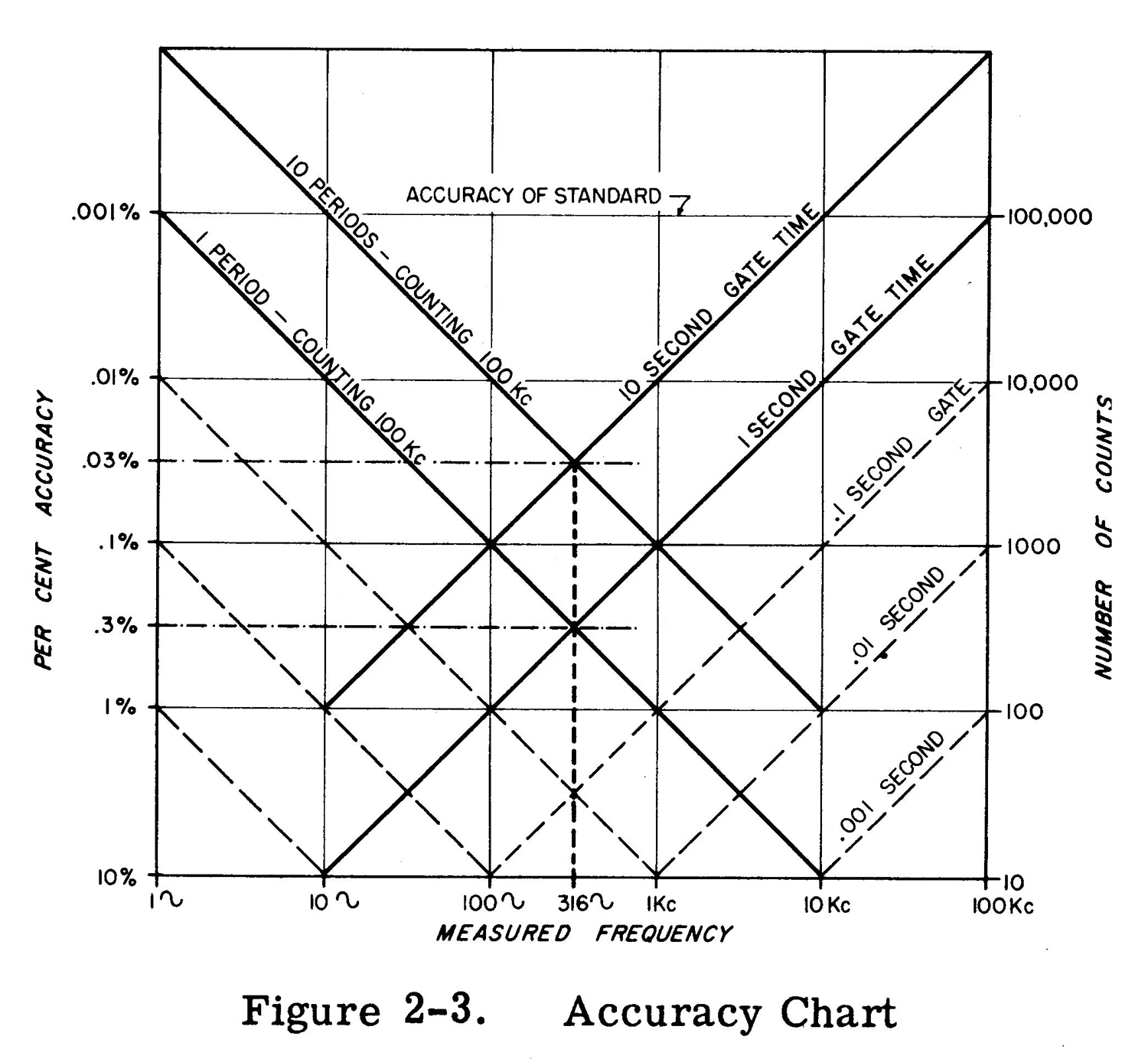
The maximum possible error for the 20 kc example is  ± .0005 percent  ± .001 percent, the two being additive in the worst case. Therefore, the greatest possible error would be .0015 percent. Due to the possible error of  ± 1 count, as the measured frequency becomes lower, the percentage error becomes higher. For a 10-cycle wave on a 1-second gate the accuracy is ±10 percent. For low frequencies the period of the waveform should he measured.
Period Measurements
On both PERIOD and 10 PERIOD AVERAGE the TIME UNIT switch will select the counted frequencies which range from 100 kc to 1 cps. Referring again to the chart of Figure 2-3, it will be noted that the greatest accuracy of period measurement is obtained on 10 period average when counting 100 kc. This of course gives the greatest total number of counts. It should be stressed at this point that the greatest accuracy for period measurement is obtained from waveforms having a sharp rise time or high slope as they pass through the zero axis. Square waves or pulses usually meet this requirement. On a sine wave or other low slope waveform the accuracy of period measurement is limited by the ability of the input circuits to trigger at the same point on consecutive cycles. The period accuracy for a sine wave is as follows: Max Error in percent = (23 × Peak noise voltage) / (No. of Periods × RMS signal voltage). Both internal and external noise voltages contribute to the errors. The internal noise voltage is  approximately 5 mv peak. Therefore, during PERIOD measurements an accuracy of .3 percent can be expected for a 1 volt rms sine wave with 10 mv noise. This accuracy can be improved by greater amplitude of input signal or by measuring a greater number of periods. Thus for a 1 volt rms sine wave on 10 PERIOD AVERAGE the accuracy expected would be .03 percent. On 10 PERIOD AVERAGE with a 10 volt rms signal containing 1 percent noise the maximum possible error would then be .003 percent. The line marked 1 Period – Counting 100 kc on Figure 2-3 is also for 10 Period – Counting 10 kc. Similarly the next lower line (dotted line running from 1 kc to .01 percent) is 1 Period – Counting 10 kc and also 10 Period – Counting 1 kc. The next line is 1 Period – Counting 1 kc and 10 Period – Counting 100 cps. This chart could be extended down and to the left to a measured frequency of .0001 cps. It will be noted that the period curves and the frequency curves cross at 316 cycles measured frequency. Thus, for frequencies above 316 cycles direct measurement of frequency gives the greatest accuracy. Below 3l6 cycles period measurements should be used.
Time Interval Measurements
There are three factors contributing to the accuracy of time interval measurements.
a. The stability of the 100 kc standard which is ± .001 percent.
b. The ambiguity of ±1 count.
c. A time error due to input slope.
Where the START and STOP inputs are sloping waves, the largest error is usually due to the inability of the  input circuits to trigger consistently at the same point. With a setting of zero volts trigger level, the overall accuracy should be:
Maximum error ± .001 percent ± period of counted freq. ± sum of times required for start and stop voltages to change 1 volt.
As the trigger level is increased either positive or negative, attenuation of input signal is introduced. The slope error increases as attenuation is introduced. At a trigger level of 100 volts the attenuation is approximately 5 to 1, at 30 volts about 2.7 to 1, and at 10 volts about 1.6 to 1.
Example:
A measurement of time interval is being made where the start voltage has a rise of 1 volt in 120 μsec. and the stop voltage has a rise of l volt in 5 μsec. at the trigger point.
If the time measured is about 500 milliseconds when counting 100 kc, the largest error would be
± .001 percent of 500 rms = ± 5.0 μsec.
± period of 100 kc               = ±  10 μsec.
±  (120 μsec. + 5 μsec.)       = ± 125 μsec.                              Maximum possible error     = 140 μsec.
There is a maximum error of 140 μsec. out of the
500.00 milliseconds measured, this is a maximum
error of .028 percent.»
§§§
Il testo prosegue nella seconda parte; per consultarla scrivere “522B” su Cerca.
Foto di Claudio Profumieri, elaborazioni e ricerche di Fabio Panfili.
Per ingrandire le immagini cliccare su di esse col tasto destro del mouse e scegliere tra le opzioni.


Oscilloscope Metrix Mod. 225 N° 075 3ème partie


Oscilloscopio Metrix Mod. 225 N° 075.  Terzaa parte.
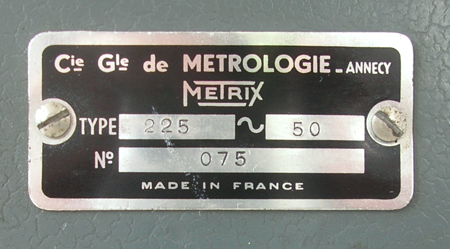
Nell’inventario D  del 1956, in data 1 settembre 1961, al n° 1981 si legge: “Ing. Ugo De  Lorenzo e Co. – Milano [importatore, N. d. R.], oscillografo Metrix mod. 225 N° 075. ₤ 390 000 . Prima destinazione: Rad”.
Il testo continua dalla seconda parte.
§§§

« 4-5 ALIMENTATION BASSE TENSION.
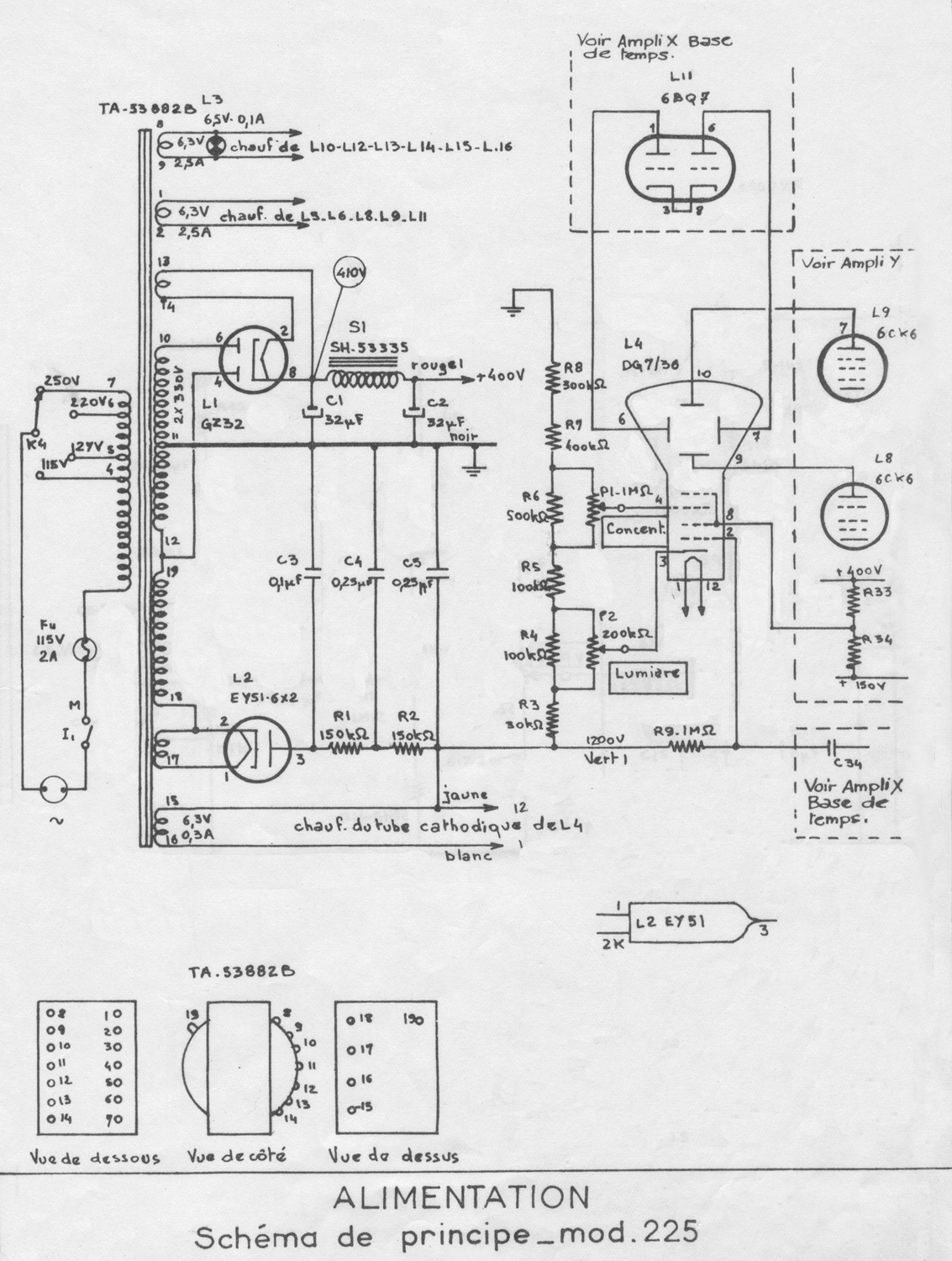
L’alimentation générale + 400 V est obtenue à partir du réseau par un redressement double alternance L1 suivi de filtrage (C1 C2 et S1 )
D’autre part, la tension d’alimentation du préamplificateur vertical est
stabilisée par une lampe au néon L7 .

CHAPITRE V
DESCRIPTION.

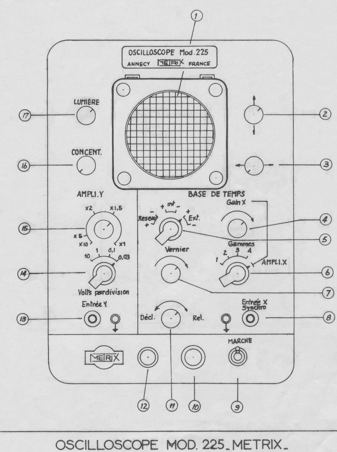
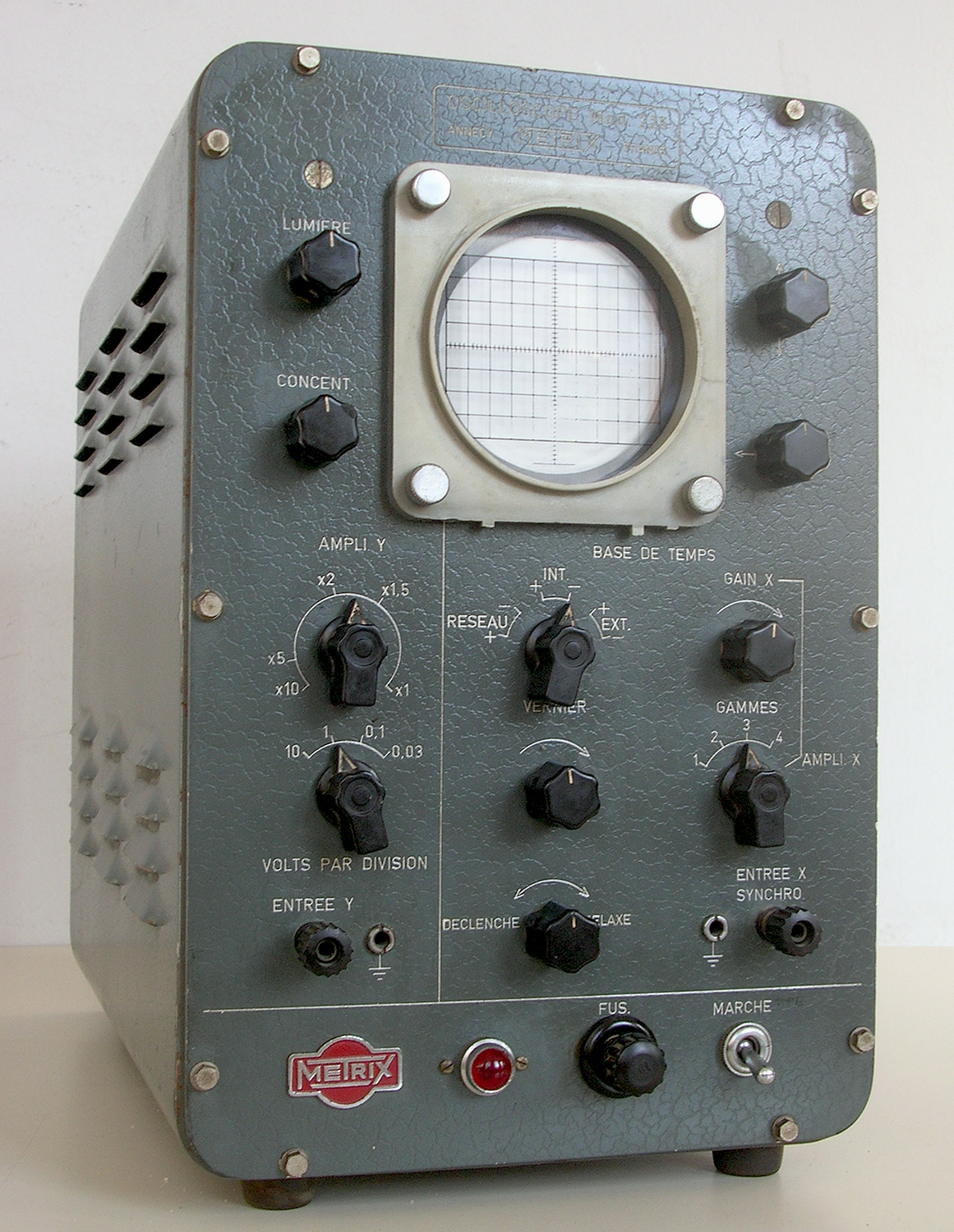
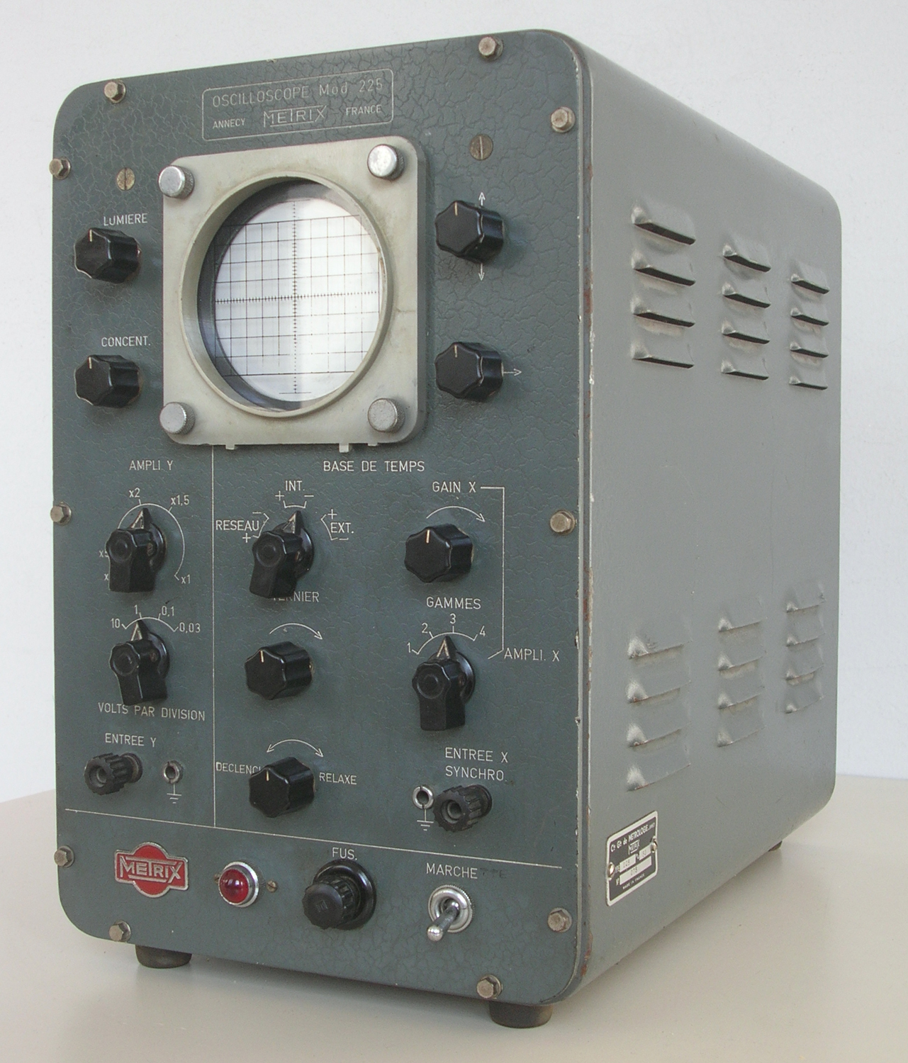
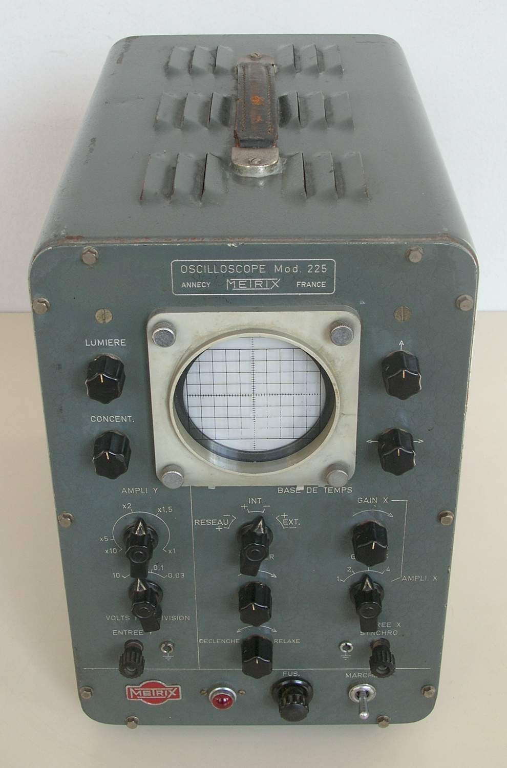
5.1 – Platine avant. On distingue successivement :
5.1.1. L’écran de l’oscilloscope (1) et ses accessoires :
un protège tube en caoutchouc
un graticule gravé sur plexiglass incolore de 10 carreaux sur 10 carreaux.
un fixe plexiglass rendu solidaire de la platine avant par 4 vis moletées.
un cache soleil
5.1.2. Le bouton de cadrage vertical du spot (2) qui commande le potentiomètre P4.
5.1.3. Le bouton de cadrage horizontal du spot (3) qui commande le potentiomètre P7.
5.1.4. Le bouton de commande gravé “gain X” (4) qui commande le potentiomètre P6 et règle le niveau d’attaque à l’entrée de 1’ampli X.
5.1.5. Le commutateur (5) de synchronisation qui permet de synchroniser le balayage.
par le signal observé
par la tension du réseau
par des impulsions fournies à la fréquence du phénomène observé.
5.1.6. Le commutateur Gammes – Ampli X (6) permet de sélectionner quatre gammes de balayage repérées 1 – 2 – 3 – 4 ou d’utiliser 1’amplificateur, le balayage étant supprimé.
5.1.7. Le vernier (7) agit sur le potentiomètre P8 qui fait varier la constante de temps RC de balayage et permet ainsi un règlage progressif de la fréquence de balayage.
5.1.8. Les bornes Entrée X Synchro. (8) qui permettent:
1° – sur la position “Ampli X” du commutateur (6) d’attaquer par un
signal extérieur l’amplificateur X.
2° – sur les positions “Gammes” de synchroniser le signal par un signal
extérieur.
5.1.9. L’interrupteur (9) met en route l’appareil sur la position repérée
“MARCHE” .
5.1.10 Le porte-fusible (10) avec un fusible 2 A. pour 115 V. ( et de 1 A sur 220 V)
5.1.11 Le bouton de commande (11) qui règle le potentiomètre P9 pour adapter le temps de retour du spot et observer à un instant donné le départ d’un phénomène sur la position déclenchée une seule dent de scie
peut être transmise.
5.1.12 Le voyant L3 (12) qui signale la mise en route de 1’appareil interrupteur sur “MARCHE”.
5.1.13 Les bornes entrée Y.(13) qui permettent d’attaquer l’amplificateur Y par le signal à observer.
5.1.14 Le commutateur (14) permet de règler la sensibilité de l’ampli vertical par sauts.
5.1.15 Le bouton de commande (15) règle progressivement le gain de l’amp1i Y  par le potentiomètre P5. On doit multiplier la sensibilité affiché par le commutateur (14) par le facteur gravé sur la platine, correspondant au repère blanc gravé sur le bouton (15 ).
5.1.16 Le bouton concentration (16) commande le potentiomètre P1 qui règle la concentration du faisceau électronique du tube cathodique.
5.1.17 Le bouton lumière (17) commande le potentiomètre P2 et règle l’intensité du faisceau électronique du tube cathodique.
5-2 – LA PARTIE ARRIERE comporte:
1° – Une entrée pour fiche femelle secteur standard.
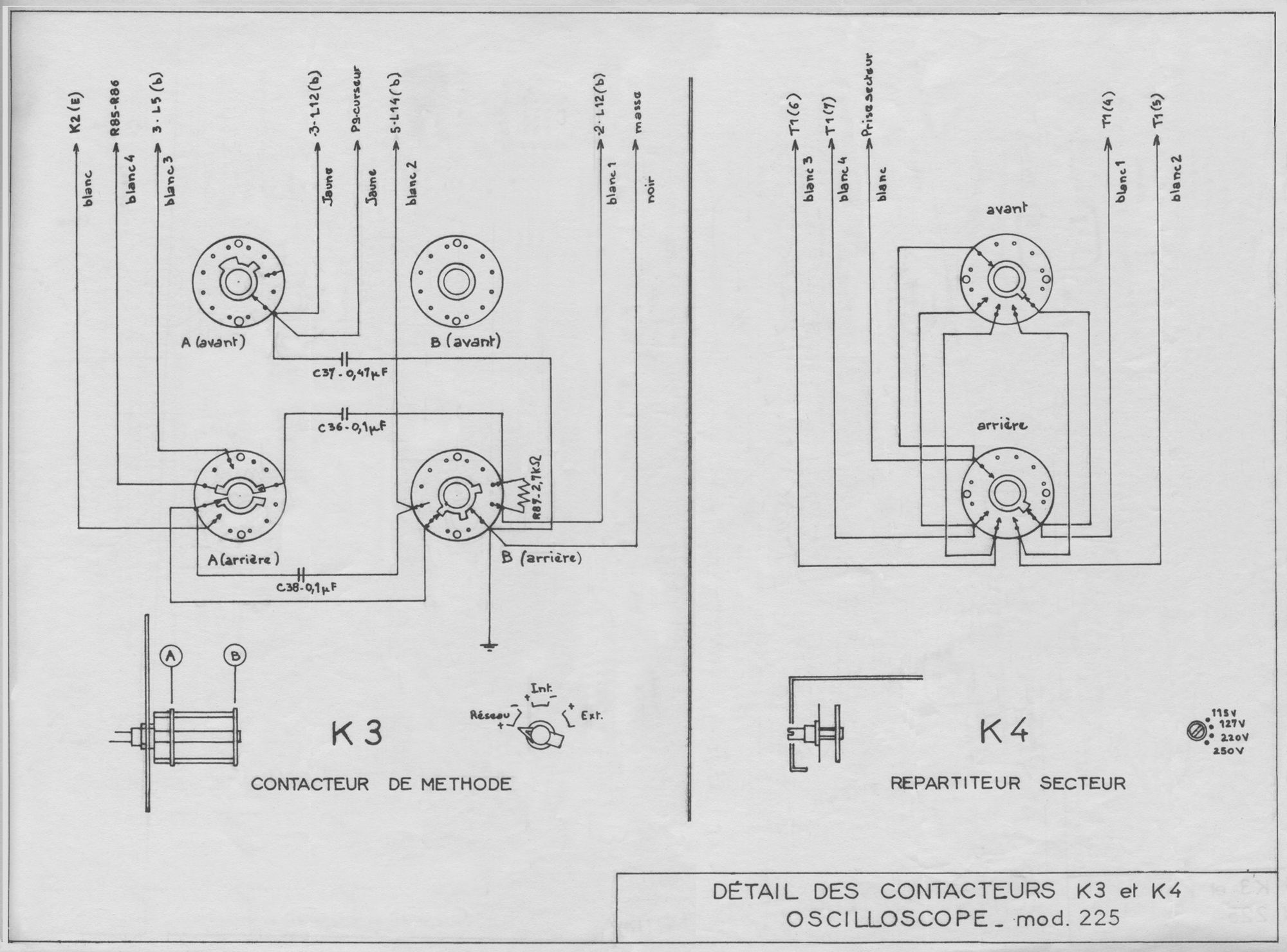
2° – Un commutateur K4 pour adapter la tension secteur à la valeur voulue 115 – 127 – 220 – 250 V. Le commutateur se règle à l’aide d’un tournevis en amenant la fente dans l’axe du repère correspondant à la tension secteur désirée, qui est gravée sur la partie arrière du coffret.
Le coffret est fixé au chassis oscilloscope par 10 vis situées sur la
face avant de l’appareil. Il est muni de volets d’aération.
Pour retirer l’appareil de son coffret, le faire glisser après avoir ôté les 10 vis de fixation (clef à tube de 6) sur les rampes de guidage
placées à l’intérieur du coffret.
5.3 –  PARTIE INTERNE DE L’APPAREIL.
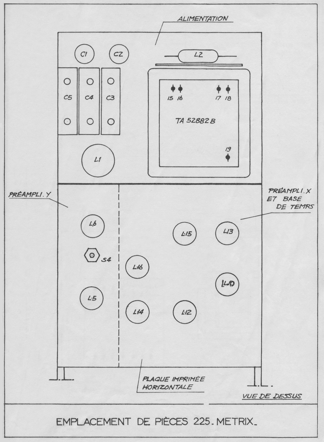
 5.3.1 – Plaquette en circuits imprimés horizontale.
Cette plaquette comporte:
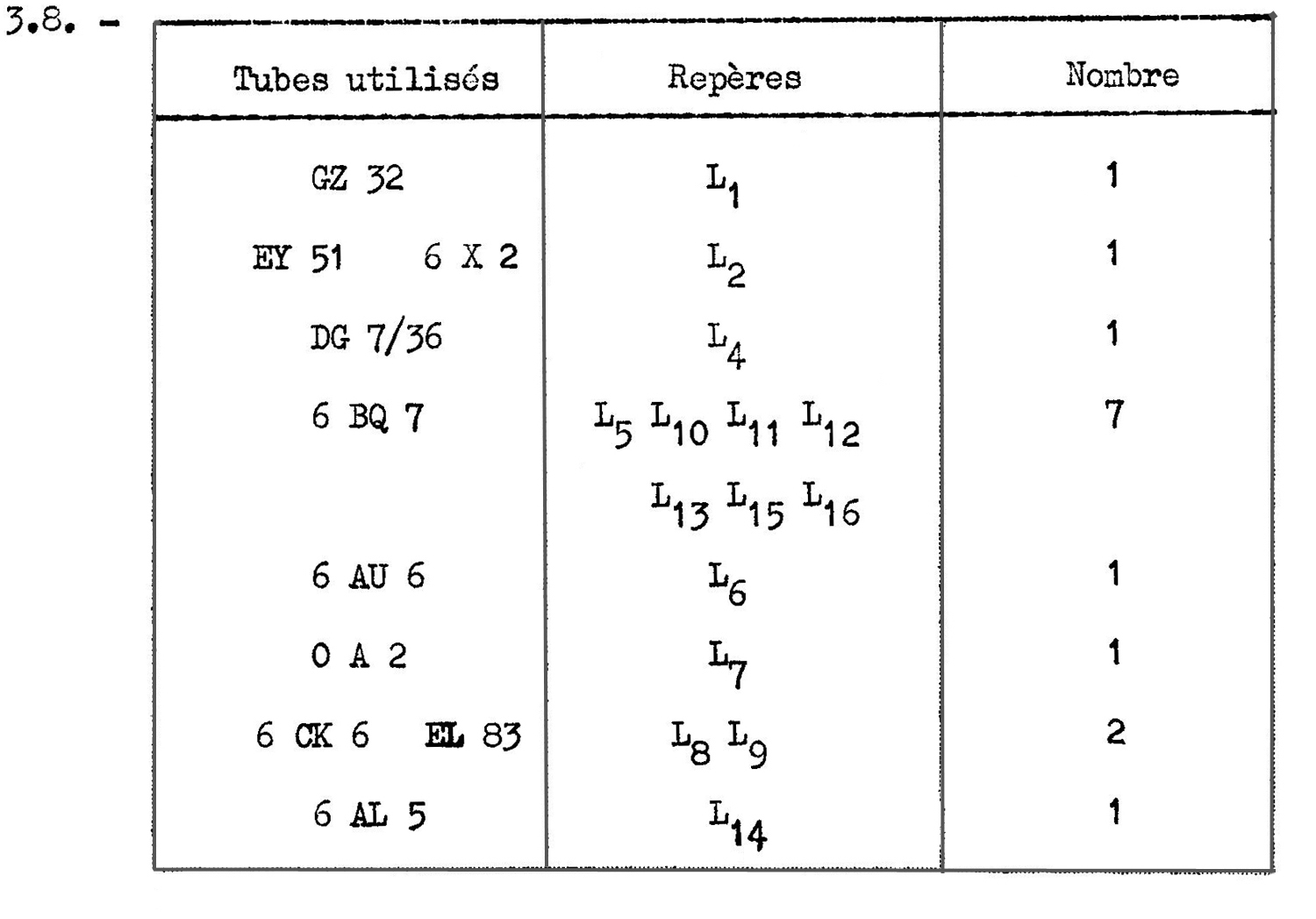
– à gauche, le préamplificateur Y avec les tubes L5 et L6 et S4 règlable.(self )
– à droite, la partie préamplificateur X et base de temps avec les tubes L10  L15  L13 L16 L14  L12.
5.3.2 – Chassis arrière horizontal. – Partie alimentation.
A gauche, les capacités de filtrage. Le transformateur d’alimentation  avec la lampe L2 (à l’arrière du transformateur, sur une plaquette en silirite) et la valve L1 .
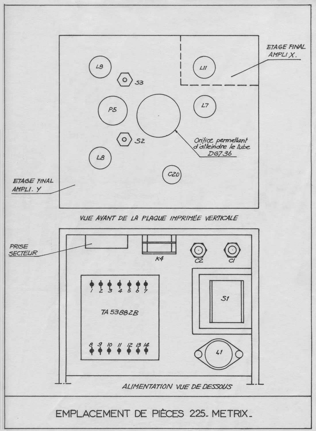
5.3.3- La plaquette en circuits imprimés verticale arrière, avec un orifice
permettant d’atteindre le culot du tube cathodique. Les étages
terminaux avec les tubes L8 et L9 (attaque des plaques de déviation
verticales) et L11 (attaque des plaques de déviation horizontales).
Le tube L7 stabilisateur de tension, de l’amplificateur Y.
Les selfs règlables repérées S3 et S2 .
Le potentiomètre P5 qui règle le gain Y en fonction des divisions
du graticule.

CHAPITRE VI
MISE EN OEUVRE

Cet appareil, alimenté sous des tensions élevées (de 1’ordre de 1500 V) est dangereux pour l’utilisateur lorsque le coffret de l’appareil est
retiré. Dans ces conditions, il convient de prendre toutes les precautions
 nécessaires pour prévenir un accident.
Avant toute utilisation, vérifier que le répartiteur secteur K4 est sur
la position correspondant à la tension du secteur utilisé : 115 – 127 – 220-250 V ~ .
On vérifiera également le calibre du fusible:
2 A pour les positions 115 – 127 V.
1 A pour les positions 220 – 250 V.
Lors d’une première utilisation, on vérifiera également que l’appareil n’a
pas souffert du transport, en retirant le coffret.
Relier alors l’oscilloscope au réseau, et abaisser l’interrupteur secteur sur la position “MARCHE”. Le voyant de mise sous tension (L3) s’allume.
6.1 – REGLAGES PRELIMINAIRES.
Tourner à fond à droite le reglage déclenché-relaxé (11), placer K2 (6)
sur l’une des positions 1 à 4.
Cadrer la ligne de balayage horizontal au centre de l’écran à l’aide du
cadrage vertical et du cadrage horizontal, situés sur la droite du tube
cathodique, et opérer les règlages de “LUMIERE” (17) et “CONCENTRATION” (16) situés sur sa gauche.
6.2. – OBSERVATION D’UN SIGNAL.
6.2.1Cas de la synchronisation intérieure:
Placer le commutateur de synchronisation (5) sur l’une des deux positions. “INT.” + ou – , selon la polarité du signal observé.
Dans le cas d’un signal sinusoïdal, l’une de ces deux positions sera choisie arbitrairement.
Choisir, à l’aide du commutateur de sensibilité et du potentiomètre de
règlage progressif du gain ampli Y (15) la position correspondant
approximativement à l’amplitude du signal examiné.
On notera que ces atténuateurs sont gradués en volts/division. Par exemple, lorsqu’ils sont placés respectivement sur 1 et ×2, chacune des divisions du graticule représente 2 V crête.
Connecter le signal à la borne d’entrée Y au moyen d’un cordon de
raccordement et retoucher si nécessaire les règlages de sensibilité de manière à ce que l’osci1logramme ne sorte pas de la zone quadrillée inscrite sur le graticule.
On règlera ensuite la vitesse du spot en agissant sur le commutateur de
gammes (6) et le vernier (7).
Pour obtenir une stabilité parfaite de l’image, on règlera le seuil du
potentiomètre “DECLENCHE-RELAXE” en tournant lentement ce règlage vers la gauche jusqu’à l’obtention d’une figure nette; au besoin, agir simultanément sur le vernier. La synchronisation parfaite doit être obtenue pour tout signal positif ou négatif donnant une déviation verticale au moins égale à une division.
Choisir par le comutateur de gammes (6) et le vernier (7) la position la
meilleure pour l’éta1ement du phénomène.
6.2.2. Cas de la synchronisation extérieure:
Le processus de règlage est celui qui vient d’être indiqué. Il faudra
toutefois placer le commutateur de synchronisation sur l’une des positions “ + ” ou “ – ” marquées “EXT.” et relier la borne de synchronisation (ENTREE-SYNCHRO.) au signal utilisé à cet effet. (Tension de synchronisation  ≥ 5 V)
6.2.3. Cas de la synchronisation par le réseau:
Lorsqu’on examine un phénomène dont la période ou la fréquence de répétition est liée au réseau, il est comode de pouvoir synchroniser directement la base de temps sur le réseau lui-même. C’est le cas de 1’étude du bruit de fond des alimentations ou de phénomènes liés à la fréquence image en télévision. A cet effet, le commutateur de méthode de synchronisation (5) sera placé sur l’une des positions “ + ” ou “ – ” RESEAU.
La permutation de polarité peut permettre, dans certains cas, un examen du phénomène dilaté en faisant varier la phase de 180°.
6.2.4. Utilisation en Ampli X:
Lorsqu’on désire substituer au signal de balayage un signal extérieur quelconque, pour réaliser par exemple une figure de LISSAJOUS, il convient de mettre le commutateur de méthode sur la position “AMPLI X”.
Appliquer alors le signal sur la borne “ENTREE X – SYNCHRO.” et règler son niveau par le jeu de P6 ( GAIN X).
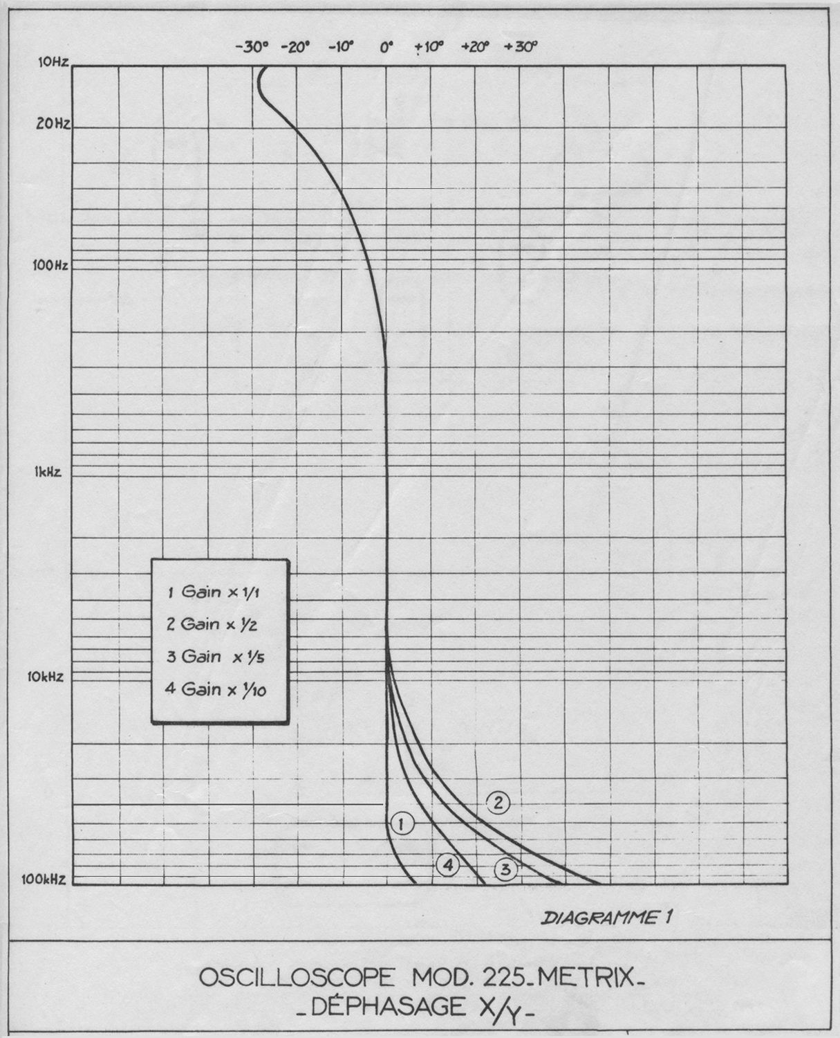
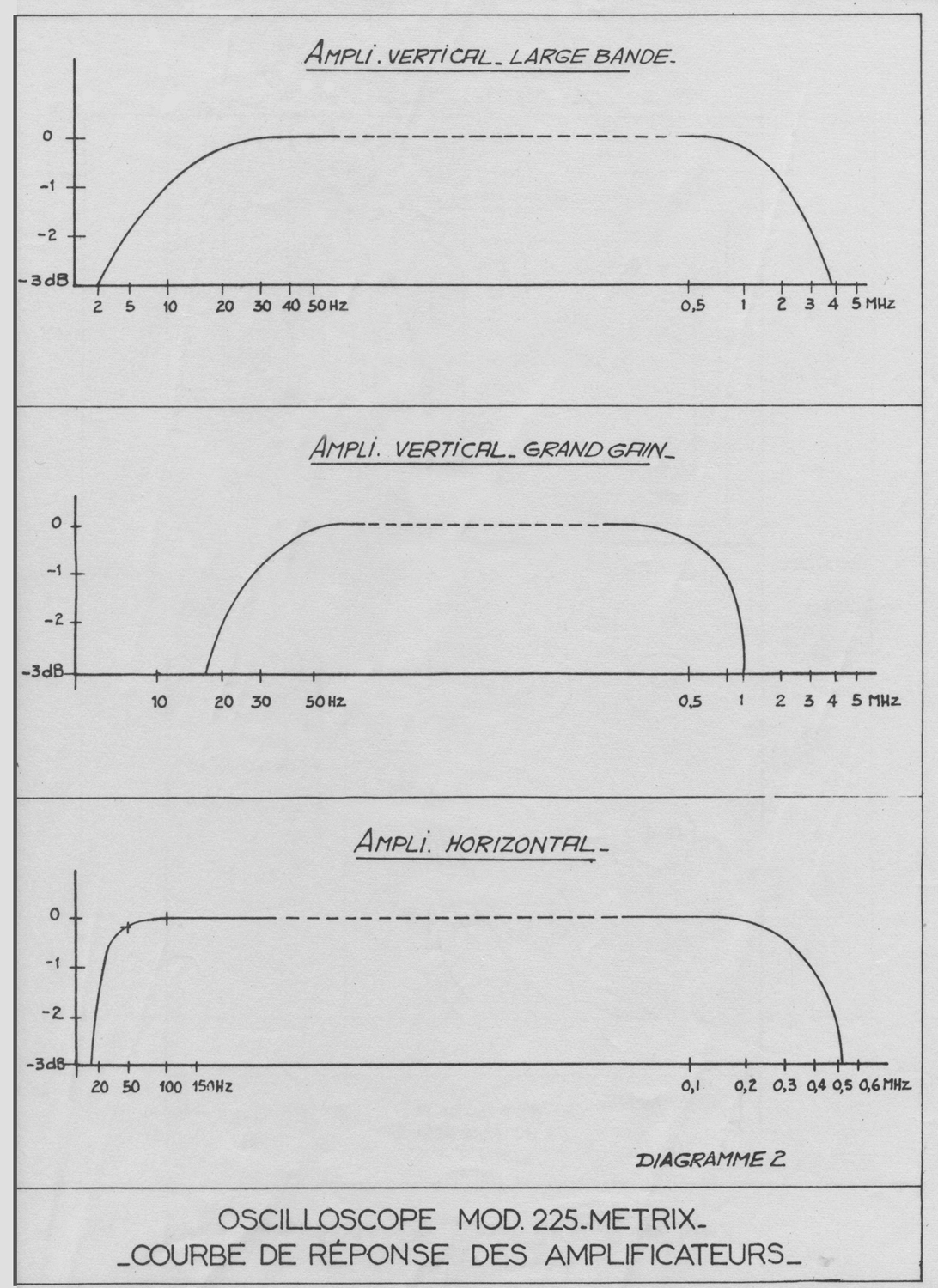
Remarque: Pour observer le déphasage entre deux signaux de même fréquence tenir compte du déphasage apporté par les amplificateurs auxfréquences extrêmes. (Voir Diagramme 1).»

Abbiamo omesso il capitolo VII.
Per consultare le altre due schede scrivere  “225 N° 075” su Cerca.
Elaborazioni e ricerche di Fabio Panfili.
Per ingrandire le immagini cliccare su di esse col tasto destro del mouse e scegliere tra le opzioni.


Oscilloscope Metrix Mod. 225 N° 075 2ème partie

Oscilloscopio Metrix Mod. 225 N° 075. Seconda parte.
 Nell’inventario D  del 1956, in data 1 settembre 1961, al n° 1981 si legge: “Ing. Ugo De  Lorenzo e Co. – Milano [importatore, N. d. R.], oscillografo Metrix mod. 225 N° 075. ₤ 390 000 . Prima destinazione: Rad”.
 Le istruzioni, conservate nell’archivio della sezione Elettronica, proseguono dalla prima parte.
§§§

«CHAPITRE IV
 FONCTIONNEMENT

4-1 TUBE CATHODIQUE ET SON ALIMENTATION.
Le tube cathodique à forte sensibilité pour mesures est du type DG 7/36.
La tension de l’anode accélératrice est de 1.450 V. Cette haute tension
est obtenue à partir du réseau par un redressement monoalternance, à
l’aide de la valve 6X2 (L2). Le filtrage de la tension redressée est
obtenu
a l’aide de C3 C4 C5 – R1 et R2 .
Le potentiomètre P2 (Lumière) permet le règlage de la luminosité et le
potentiomètre P1 (concentration) le règlage optimum de la finesse du spot.
Ces règlages sont accessibles de la platine avant.

4-2 AMPLIFICATEUR DE DEVIATION VERTICALE.
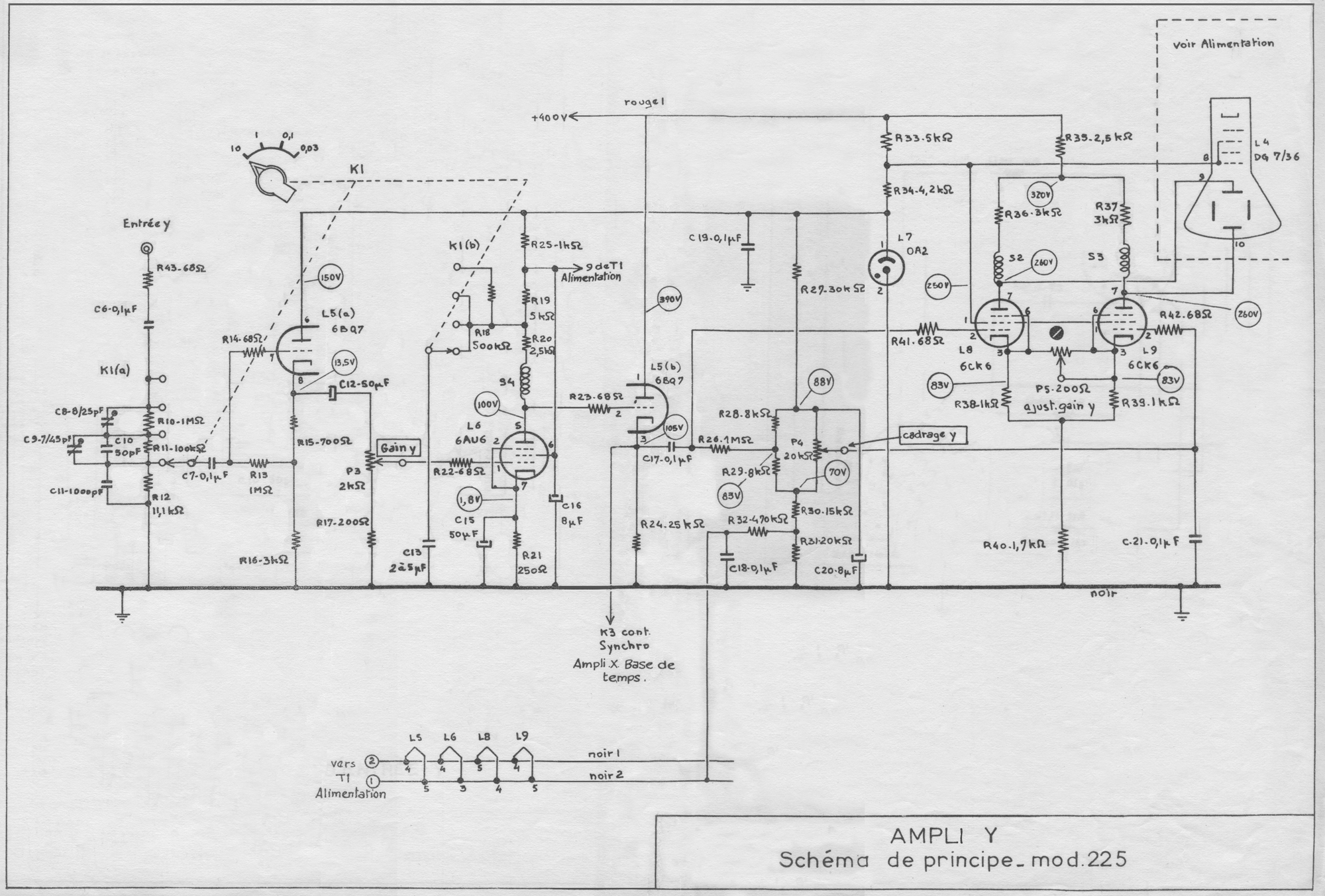
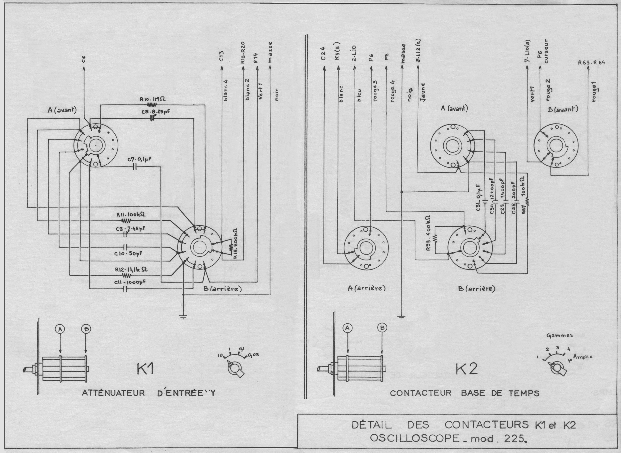
Le signal appliqué aux bornes de l’entrée Y ( la composante continue éventuelle est éliminée par C6 ) est atténué par un atténuateur à plots K1
(rapports 1 – 10 – 100). Ce commutateur permet de prélever une fraction
du signal d’entrée. Les capacités C8, C9, C11 rendent l’atténuation
indépendante de la fréquence.
Il attaque ensuite le cathode follower L5 (a) dans la cathode duquel on a
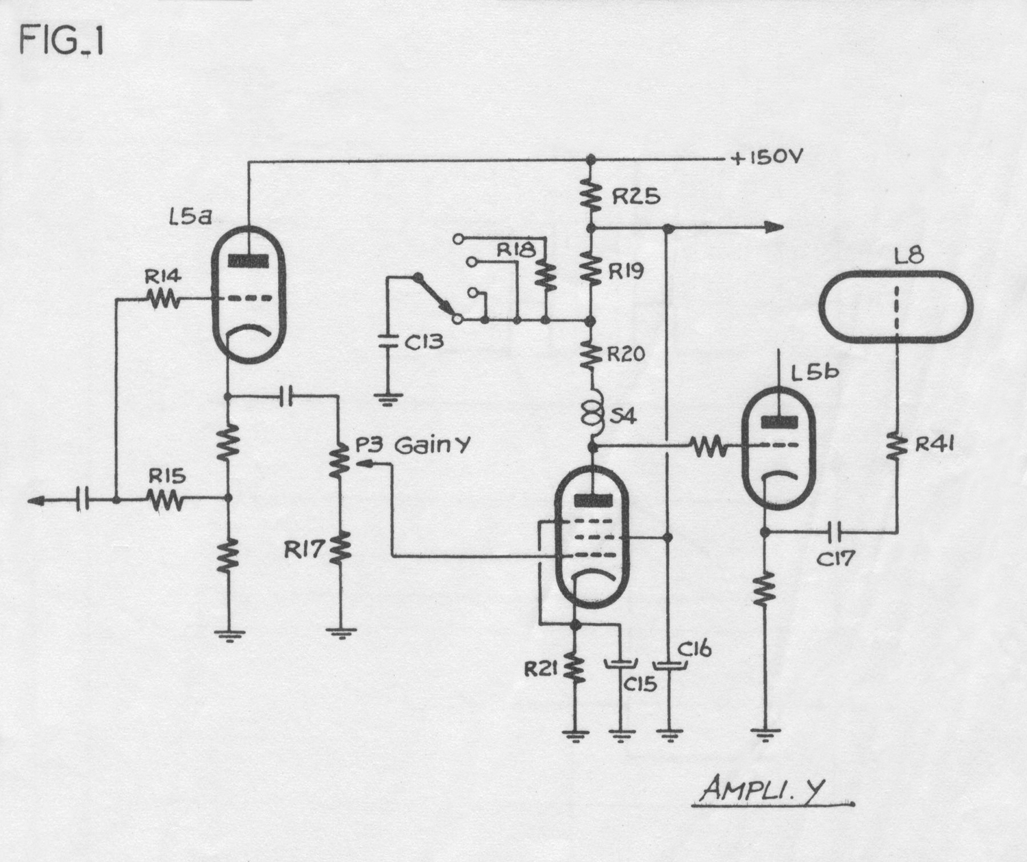
disposé un potentiomètre de faible valeur constituant un règlage progressif de gain, indépendant de la fréquence. L’étage suivant fonctionne de la manière suivante: (fig. 1 des schémas partiels).

Sur les positions 0,1 – 1 – 10 de K1 , la résistance de charge de la 6AU6
est constituée par R19 et R20, R19 étant shuntée par le condensateur C13.
Aux fréquences élevées, 1’impédance présentée par C13 est nulle et shunte R19, la charge subsistant est R20.
Lorsque la fréquence diminue, l’impédance de C13 augmente et la charge augmente, le gain devient plus important, ce qui permet d’amplifier des signaux
de fréquence très basse ( 2 Hz à 3 dB), malgré l’affaiblissement apporté par l’impédance des capacités de liaison.
Sur la position 30 mV par contre, on élimine le rôle de C13 du fait de
1’adjoncticn d’une forte résistance R18 en série. Le gain aux fréquences
moyennes est multiplié par 3,3. (rapport [R19 + R20 ] / R20 ) mais il n’y a plus de correction aux très basses fréquences. La bande passante est limitée dans sa partie inférieure à 20 Hz.
La self S4 permet d’améliorer la courbe de réponse pour les frequences elevées.
Le signal obtenu est transmis par l’intermédiaire du cathode follower L5 (b) à 1’amplificateur final L8 L9 (voir schéma de principe Ampli Y ).
L’étage final est un amplificateur symétrique à liaison cathodique. Le signal appliqué à la grille L8 se trouve amplifié entre les anodes de L8
et L9. De là, il attaque les plaques de déviation verticales Y1 et Y2.
Les selfs S2 et S3 permettent de corriger l’amplification aux hautes fréquences.
Le potentiomètre P4 (cadrage Y) permet d’appliquer une tension continue variable sur la grille L9. La liaison entre 1’amplificateur symétrique et le tube cathodique étant directe, le cadrage vertical du spot s’effectue sans constante de temps.
4-3 BASE DE TEMPS.
La base de temps comprend:
– un générateur de tension en dents de scie.
– un ensemble de lampes de commande et de circuits de synchronisation.
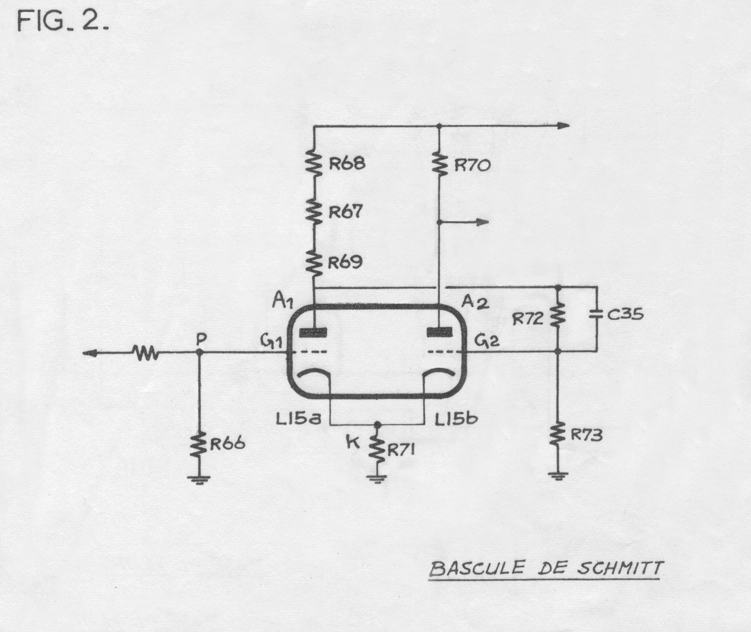
Pour comprendre le fonctionnement de la base de temps, analysons au préalable le comportement d’un de ses éléments, la bascule de SCHMITT.
4.3.1. Fonctionnement de la bascule de Schmitt. (voir fig. 2 des Schémas  partiels).
Le principe général consiste à produire sur la plaque A2 du tube L15b une tension rectangulaire, en faisant varier le courant de ce tube d’une valeur maximum à une valeur zéro. Cette tension, est prélevée sur une résistance R70 insérée dans le circuit plaque de L15b.
Pour cela, on applique le signal en dents de scie à la grille d’un tube
L15a qui, initialement, est bloqué lorsque L15b débite.
Lorsque le potentiel en P, Vg1 atteint une valeur V1, le tube L15a commence
à débiter. Va1 diminue du fait de la liaison entre la plaque A1 de L15a et
la grille G2 de L15b, Vg2 diminue, et L15b se bloque par effet cumulatif
(liaison réalisée par le diviseur R72 R73).
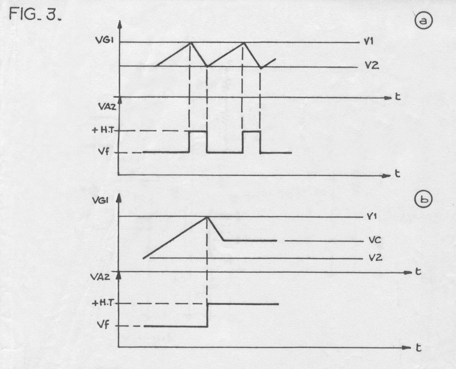
La bascule a changé d’état et le potentiel Va2 de la plaque est passé
d’une valeur Vf à la valeur + H.T. . Cette impulsion provoque la décharge de la capacité de balayage (la méthode adoptée est exposée dans le paragraphe 4. 3.20.)
La tension en P diminue alors jusqu’à un seuil V2 <  V1 pour lequel le
courant diminuant dans le tube L15a provoque une remontée du potentiel Va1, donc de Vg2 suffisante pour produire le déblocage du tube L15b.
La tension sur A2 , Va2 retombe à sa valeur initiale Vf (voir fig. 3 (a)
des schémas partiels).
La décharge de la capacité de balayage cesse alors (voir explications du
paragraphe 4.3.2.) et le cycle peut alors se reproduire.

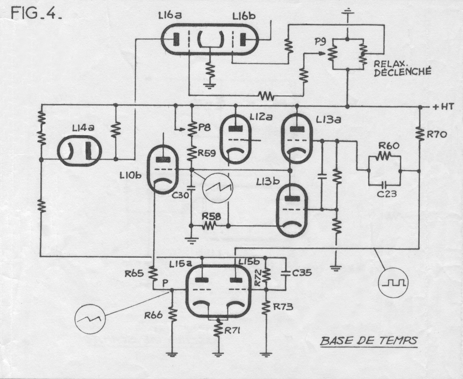
4.3.2. Fonctionnement de la base de temps. (voir fig. 4 des schémas
partiels).
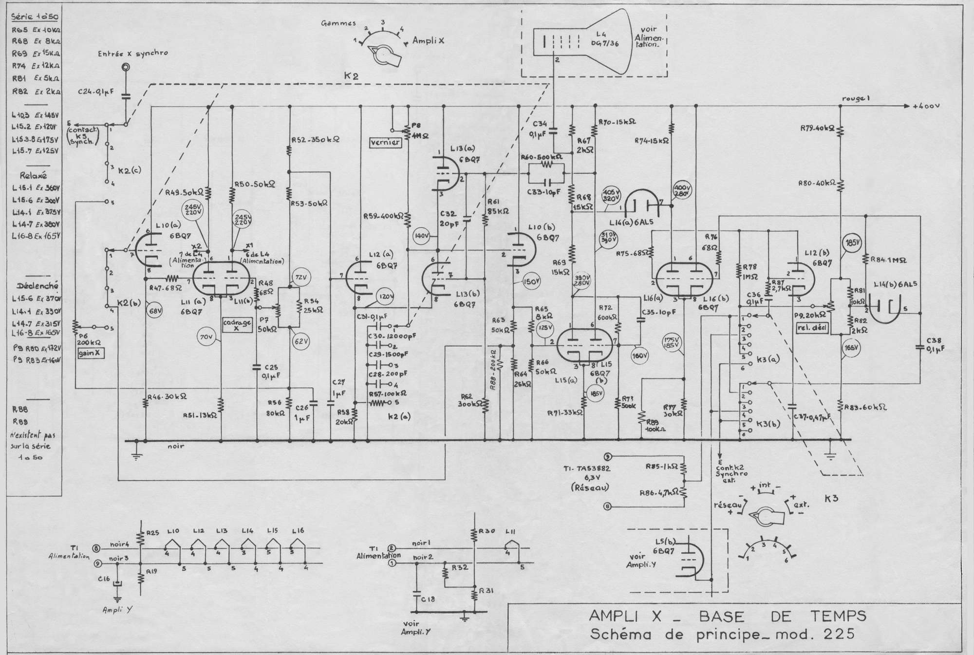
La dent de scie est obtenue par la charge (sous une tension suffisamment élevée) de l’une des capacités de balayage C28 à C31 à travers P8 (vernier) et R59. Cette partie du signal est utilisée pour le balayage horizontal  du tube, linéairement en fonction du temps. Le retour à l’état initial s’opère par la décharge de ces capacités à travers L13b .
A – Fonctionnement en position relaxée (voir fig. 4 des schémas partiels).
Le condensateur C30, capacité de balayage se charge sous + H.T. à travers P8 et R59. L’augmentation de potentiel est transmise sur la grille, puis sur la cathode de L10b (cathode follower) ce qui entraîne la variation du potentiel en P.
Supposons la bascule de Schmitt dans l’état initial. L15b conduit, L15a est bloqué, le système bascule lorsque Vg1 (L15a) atteint le potentiel V1  ( + 170 V environ).
L15b se coupe, la grille de L13b dont le potentiel est fixé par la cathode de L12a, reçoit une augmentation de potentiel dûe à l’augmentation du potentiel Va2 transmise lors du blocage.
L13b conduit et la décharge de C30 est amorcée. Puis le potentiel en P
décroit jusqu’à V2 pour lequel L15 bascule à nouveau. L15b se met à conduire donc L13b se coupe (le potentiel e A2 est retombé à Vf) et la capacité se recharge à nouveau.
Fonctionnement en déclenché.
Il n’y a pas de changement pour la charge et la décharge de la capacité
de balayage, pourtant à la fin de la décharge, la bascule de Schmitt
ne change pas d’état.
Considérons la figure 3 (b).
Pour agir sur le niveau V2 seuil de basculement inférieur de L15 , on
peut agir sur la tension plaque Va1 du tube L15a.
Quand L15a conduit lors de la décharge, Va1 ne peut descendre au-dessous d’une certaine valeur, car la diode L14a se met alors à conduire, fixant ainsi le potentiel Va1 à une certaine valeur limite. Cette limite, dont dépend Vg2, peut être descendue de telle sorte que V2 ne puisse être atteint (valeur de Vg1 pur laquelle le tube L15b se débloque). Ce seuil est règlé par le courant du tube L16a. Plus le courant est important, plus le seuil se trouve bas. Le potentiel de la plaque Va1, et par suite
V2 se trouvent de même abaissés.
Le potentiomètre P9 permet de contrôler et règler ce courant, dans L16a
qui est maximum dans la position déclenchée de P9.
Si le seuil diminue (fig. 3b) la décharge se poursuit jusqu’à Vc > V2
la lampe L13a se met alors à conduire, fixant ainsi le potentiel du
condensateur à cette valeur Vc avant que L15 ne bascule, car V2 ne peut
être atteint.
Pour que la capacité de balayage se charge à nouveau, il faut provoquer
le basculement de L15. Ceci peut se faire de deux manieres:
a) Par manoeuvre du potentiomètre P9, le courant dans L16a
Le potentiel sur l’anode de L14a remonte, et L14a se met à
conduire; le potentiel Va1 de la plaque de L15a remonte, donc
V2, ce qui provoque le changement d’état de la bascule (voir
fig. 4 des schémas partiels).
b) En envoyant un signal sur l’une ou l’autre des grilles de L16,
ceci permet, d’une manière analogue, de faire varier ce courant
dans L16a. On est ainsi assuré de provoquer le départ de la
dent de soie en un point bien déterminé du phénomène à étudier
et on obtient alors une bonne synchronisation.
Pour faire diminuer le courant dans L16a, il faut appliquer des impulsions
négatives à la grille de L16a ou des impulsions positives à celles de L16b, ce qui provoquera le changement d’état de la bascule. Les diodes L12b et L14b permettent d’éliminer les impulsions de polarité contraire.
La dent de scie ainsi obtenue est transmise par l’intermédiaire du cathode follower L10a à l’ampli final X.
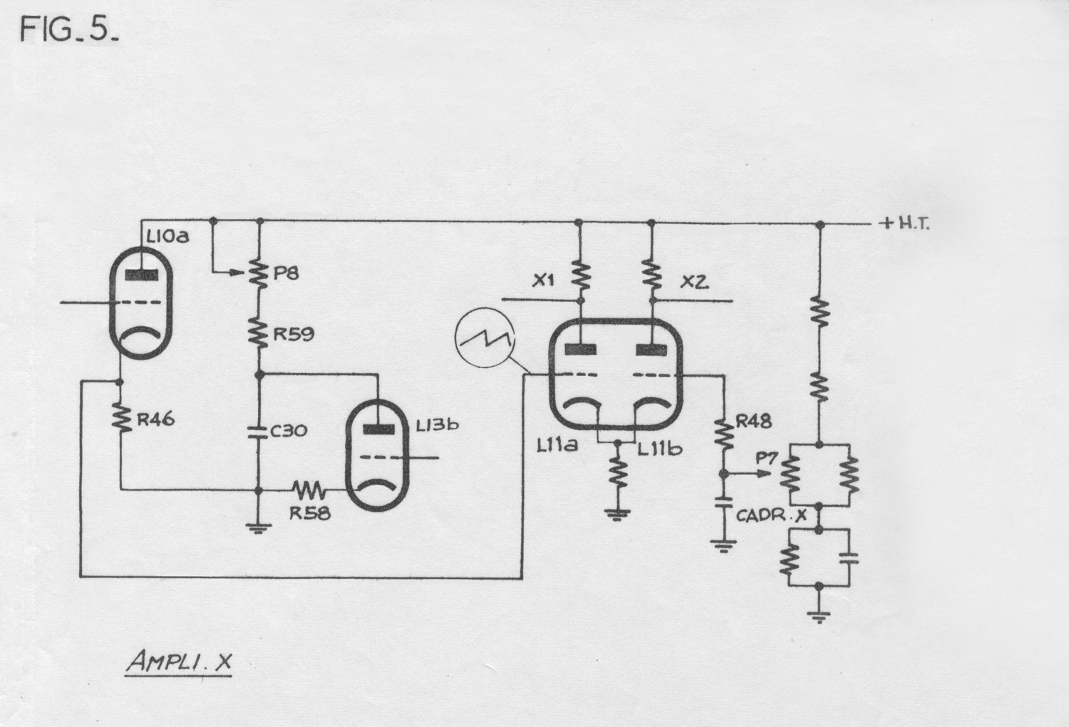
4.4-AMPLI X.
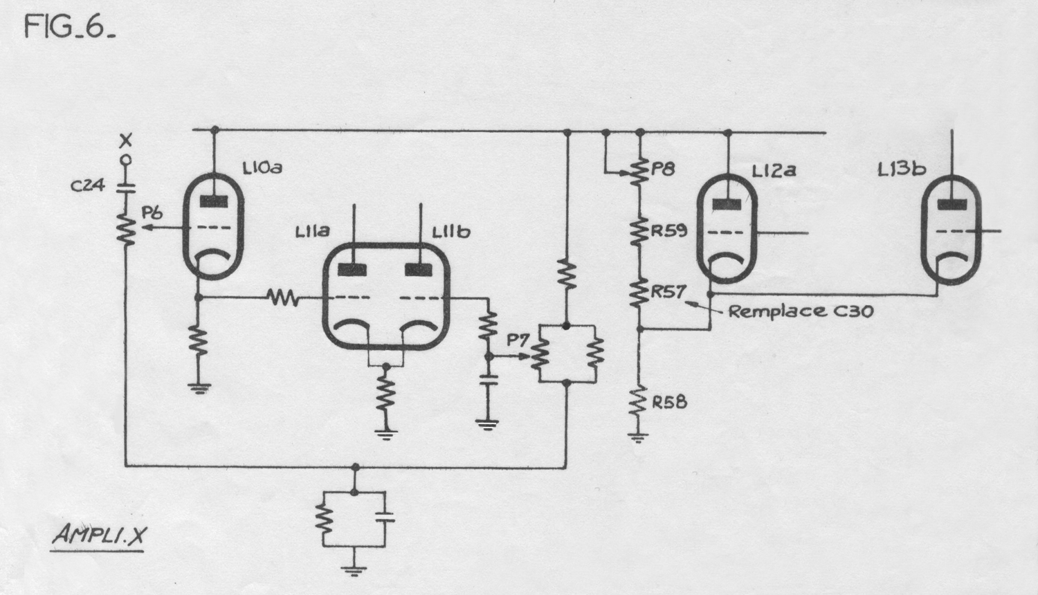
4.4.1.- L’entrée X synchro élimine par C24 toute composante continue d’un signal extérieur à observer ou utilisé pour la synchronisation. Sur l’une des positions 1 – 2 – 5 – 4 – du commutateur K2, la dent de scie est envoyée sur le cathode follower L10 (a) qui attaque l’une des grilles de l’amplificateur final L11 (voir figure 5 des schémas partiels).
Cet amplificateur est un amplificateu r symétrique à couplage cathodique. On retrouve le signal amplifié entre les plaques de L11, d’où il est appliqué aux plaques de déviation horizontales de l’ampli X.
La tension continue de la grille L11b peut être règlée par l’intermédiaire du potentiomètre P7 (cadrage X) de même que pour le cadrage Y, la liaison directe assure une réponse immédiate du cadrage horizontal du spot.
4.4.2. Sur la position 5 du commutateur K2, la grille de commande L11a est reliée par 1’intermédiaire du cathode follower L10 (a) et de P6 à la borne “Entrée X” ce qui permet de commander les plaques horizontales par un signal extérieur (obtention des figures de Lissajoux relevé d’un trapèze de modulation). Ce potentiomètre P6 assure une atténuation convenable du système.
Sur la position 5 de K2 – R57 résistance de 100 KΩ remplace C30, la capacité de balayage dans le circuit de charge.»
§§§
Il testo prosegue nella terza parte.
Per consultare le altre due schede scrivere  “225 N° 075” su Cerca.
Elaborazioni e ricerche di Fabio Panfili.
Per ingrandire le immagini cliccare su di esse col tasto destro del mouse e scegliere tra le opzioni.


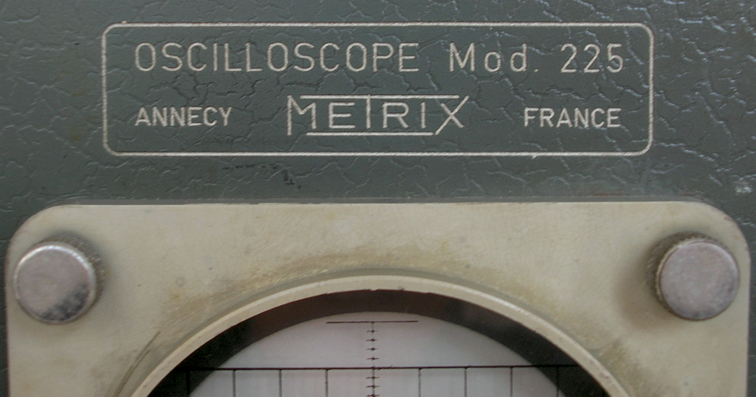
Oscilloscope Metrix Mod. 225 N° 075 1ère partie


Oscilloscopio Metrix Mod. 225 N° 075. Prima parte.
Nell’inventario D  del 1956, in data 1 settembre 1961, al n° 1981 si legge: “Ing. Ugo De  Lorenzo e Co. – Milano [importatore, N. d. R.], oscillografo Metrix mod. 225 N° 075. ₤ 390 000 . Prima destinazione: Rad”.
Riportiamo qui di seguito le istruzioni conservate nell’archivio della sezione Elettronica.
Esse proseguono nelle altre due schede.
§§§
«TABLE DES MATIERES
I- GENERALITES
II- PRINCIPE
III- CARACTERISTIQUES TECHNIQUES
IV-  FONCTIONNEMENT
V-  DESCRIPTION
VI- MISE EN OEUVRE
VII- ENTRETIEN – DEPANNAGE
NOMENCLATURE DES PIECES ELECTRIQUES
PLANCHES
Vue avant de l’appareil
Schémas de principe :
-Alimentation
-Ampli. Y
-Ampli. X – Base de temps
-Détail des contacteurs K1 et K2
-Détail des contacteurs K3 et K4
Schémas partiels :
Diagrammes:
1- Déphasage  X/Y (on fonction du gain et de la fréquence.
2 – Bandes passantes des Amplificateurs X et Y
Emplacement  des pièces
– Vue de dessus. Plaque  imprimée horizontale Alimentation.
– Vue de dessous. Alimentation et vue avant plaque imprimée verticale.

CHAPITRE I
GENERALITES.
L’oscilloscope 225 est conçu pour couvrir la gamme de mesure dans le domaine basse fréquence, moyenne fréquence et vidéo.
Sa sensibilité autorise son emploi pour 1’analyse des
circuits des
amplificateurs basse et moyenne fréquence.
Sa bande passante le rend apte à l’examen des signaux de télévision, car ses circuits de synchronisation ont été spécialement étudiés en vue d’assurer l’affichage  de signaux lignes et images, sans aucune difficulté et avec une parfaite stabilité.
L’étalonnage des sensibilités en fait un véritable instrument de mesure.
Par ses caractéristiques, l’oscilloscope 225 devient un auxiliaire précieux et indispensable pour toutes les opérations de dépannage et d’entretien sur les amplificateurs basse fréquence, chaines haute fidélité, amplificateurs de sonorisation, de cinéma, récepteurs de radiodiffusiu ou de télévision, etc…

CHAPITRE II
PRINCIPE
L’oscilloscope 225 comporte les principaux éléments suivants :
– un tube cathodique de 75 mm à fond plat.
– un amplificateur de déviation verticale étalonné en
V/division, à sensibilité contínûement variable, de 30 mV/division à 100 V/division.
– un amplificateur de déviation horizontale.
– une base de temps relaxée-déclenchée. En régime déclenché, le balayage s’effectue sans retour préalable du spot, avec allumage automatique de celui-çi.
La fonction déclenchée se fait manuellement ou par impulsions + ou –
– des circuits de synchronisation permettant de déclencher ou synchroniser la base de temps sur impulsion positive ou négative ou sur phénomène périodique, ou encore sur la fréquence du réseau d’alimentation (2 fois la fréquence image en télévision, ce qui permet une synchronisation aisée sur cette fréquence).

CHAPITRE III
CARACTERISTIQUES TECHNIQUES.
3.1- CARACTERISTIQUES DU TUBE CATHODIQUE.
-diamètre 75 mm à fond plat ( 70 mm utilisables )
– spot vert non rémanent
– type DG 7/36. A concentration électrostatique.
3.2 – AMPLIFICATEUR DE DEVIATION VERTICALE.
– tension maximum applicable 500 V ( = et crête ~)
– sensibilité maximum 50 mV crête à crête par division
-sensibilité minimum 100 V crête à crête par division.
-atténuateur à quatre positions (30 mV/division; 100 mV/division; 1 V/division; 10 V/division) 1 division = 1 carreau = 6,5 mm sur le graticule quadrillé; chaque division est divisée à son tour en 5 parties égales. Cet atténuateur est corrigé en fréquence.
– atténuateur progressif à basse impédance, permettant de faire varier la sensibilité dans le rapport 10.
– bande passante : 2 Hz – 4 MHz à 3 dB pour toute sensibilité supérieure à 100 mV crête à crête par division. 20 Hz – 1 MHz à 3 dB, de 30 mv/division à 100 mV/division (Voir Diagramme 2).
– impédance d’entrée : 1 MΩ. Capacité d’entrée < 40 pF
– étalonnage en tension à lecture directe.

3.3- BASE DE TEMPS.
– relaxée ou déclenchée sans retour préalable, assurant l’allumage automatique du spot.
– durées de balayage par division continûement variables de 1 μs/division à 5 ms/division.
– fréquence de balayage en relaxé 15 Hz à 50 kHz.
– durées limites pour la totalité du balayage : 60 ms à 15 μs.
– synchronisation intérieure ou extérieure permettant de synchroniser
le signal, soit sur une montée de signal (+), soit sur une descente (-); ou synchronisation sur la fréquence du réseau (étude du bruit de fond des alimentations, synchronisation sur la fréquence image en télévision, etc…)
– impédance d’entrée du circuit de synchronisation extérieure : 1 MΩ
3.4. – AMPLIFICATEUR DE DEVIATION HORIZONTALE.
– Tension maximum applicable 500 V ( = et crête ~)
– Sensibilité maximum = 1 V/division
– Atténuateur progressif
– bande passante au maximum de sensibilité : 20 Hz – 500 kHZ à 3 dB (Voir Diagramme 2 )
– impédance d’entrée : 200 kΩ
3.5. – ALIMENTATION.
115 – 127 – 220 – 250 V ~  ± 10 %; 48 à 63 Hz.
Consommation : 120 VA.
3.6. – DIMENSIONS : 210 × 320 × 540 mm
3.7. – POIDS  13 kg environ
3-8…. .»

Il testo prosegue nella seconda parte.
Per consultare le altre due schede scrivere  “225 N° 075” su
Cerca.
Foto di Claudio Profumieri, elaborazioni e ricerche di Fabio Panfili.
Per ingrandire le immagini cliccare su di esse col tasto destro del mouse e scegliere tra le opzioni.


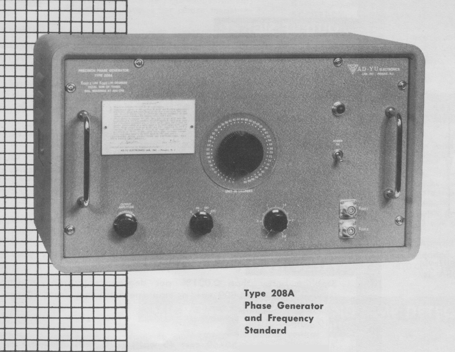
Precision Phase Generator type 208A AD-YU Electronics 2ª parte


Precision Phase Generator type 208A AD-YU Electronics, Lab Inc. Passaic N.J. . Seconda parte.
Nell’inventario D del 1956, in data  agosto 1964, al n° 3756 si legge: “Ing. MarioVianello. Milano. Circuito sfasatore “AD-YU” mod. 208A. Destinazione RAD. ₤  720.000”.
Dopo la pubblicazione delle prime due schede abbiamo trovato negli archivi altre istruzioni più dettagliate che ora si trovano nella terza parte.
Riportiamo qui di seguito tutto ciò che avevamo trovato in precedenza.
§§§


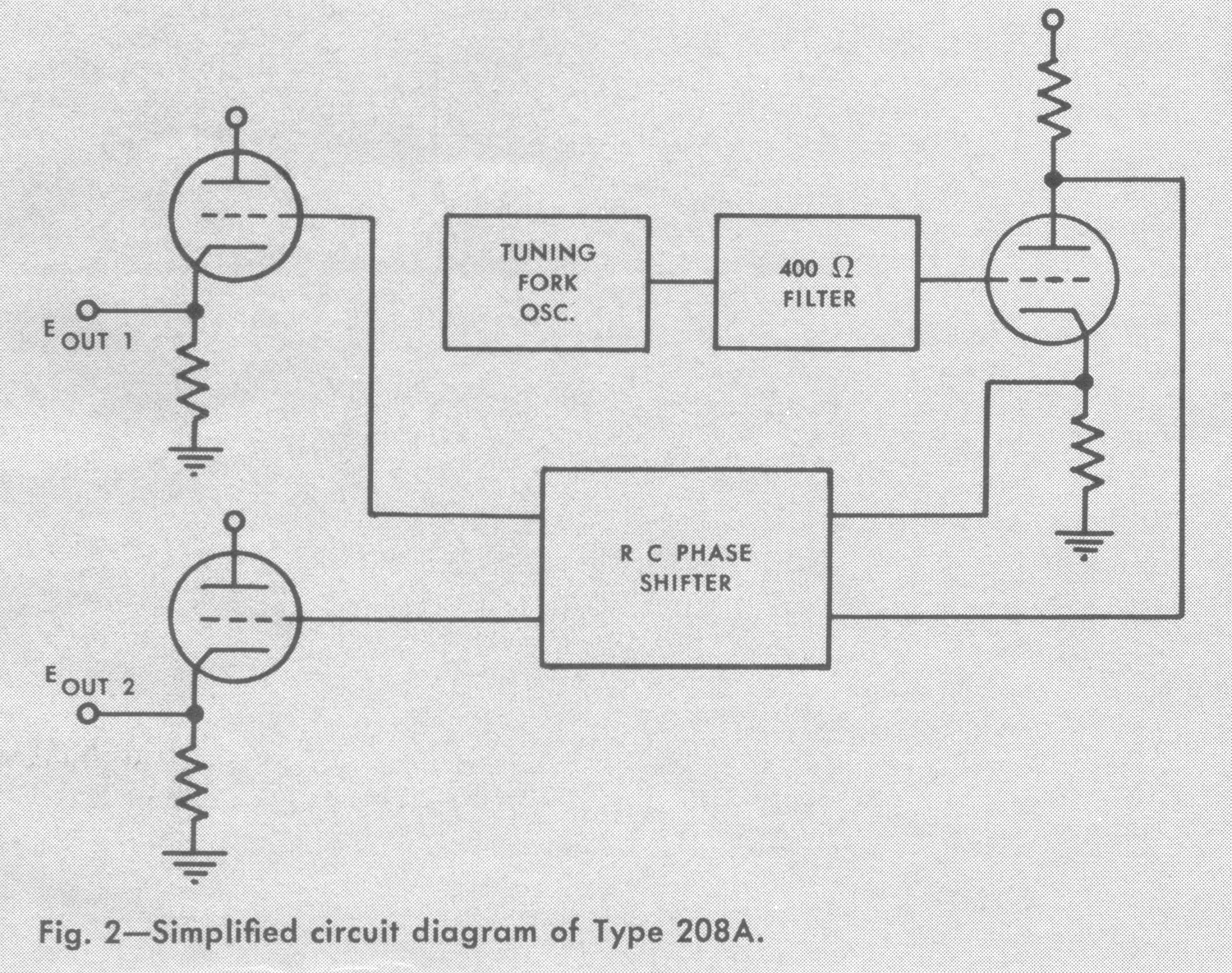
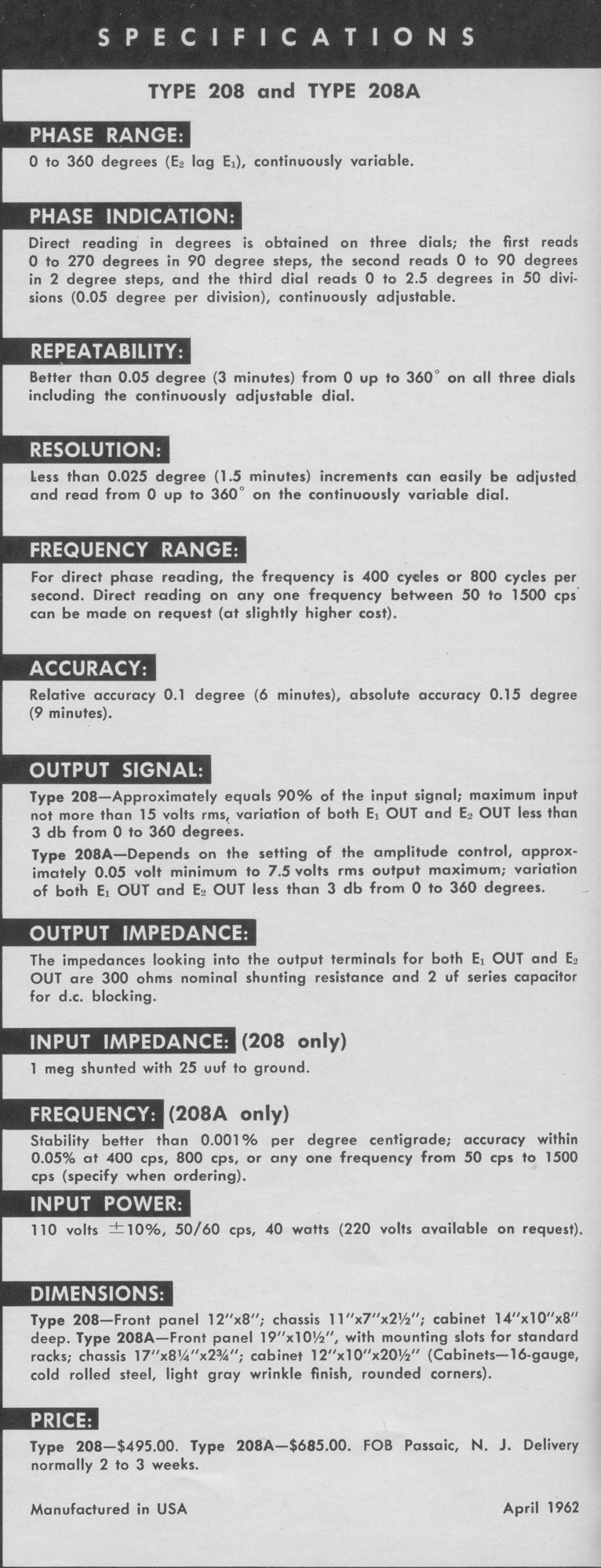
«DESCRIPTION
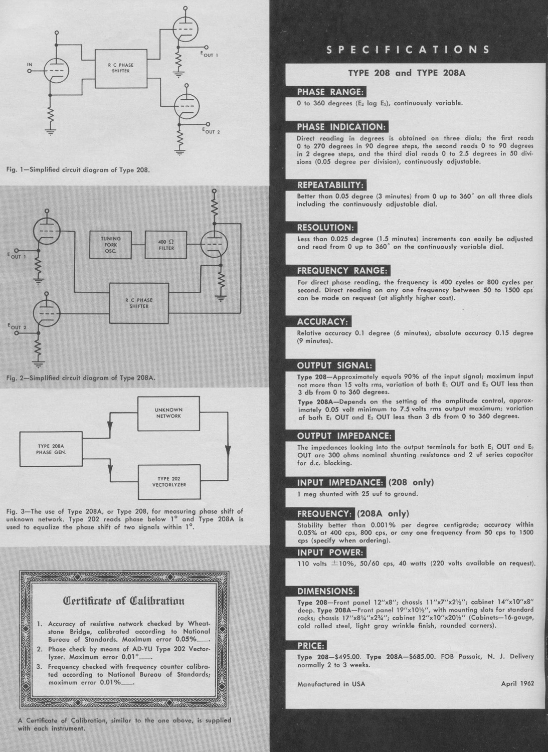
Type 208 consists of resistance-capacitance phase shifting networks, an electron-tube phase inverter, and two output cathode followers.
Type 208A is identical to Type 208, except having a tuning fork oscillator and a filter circuit. There are many applications for the
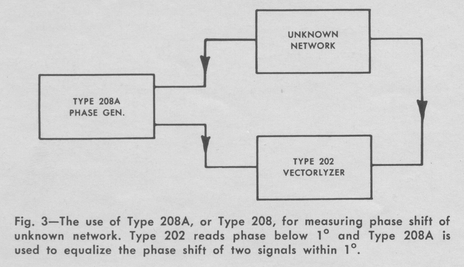
precision phase generators, for example: (1) Precision phase measurement of unknown net- works in conjunction with AD-YU Type 202 Vectorlyzer, see Fig. 3. (2) Calibration of phase meters and all other phase measuring devices. (3) Precision phase measurement between two given voltages with Type 208 and AD-YU Type 202 Vectorlyzer. (4) Type 208A may be used as a frequency standard since its stability is less than 0.001% per degree centigrade and the accuracy is within 0.05%.


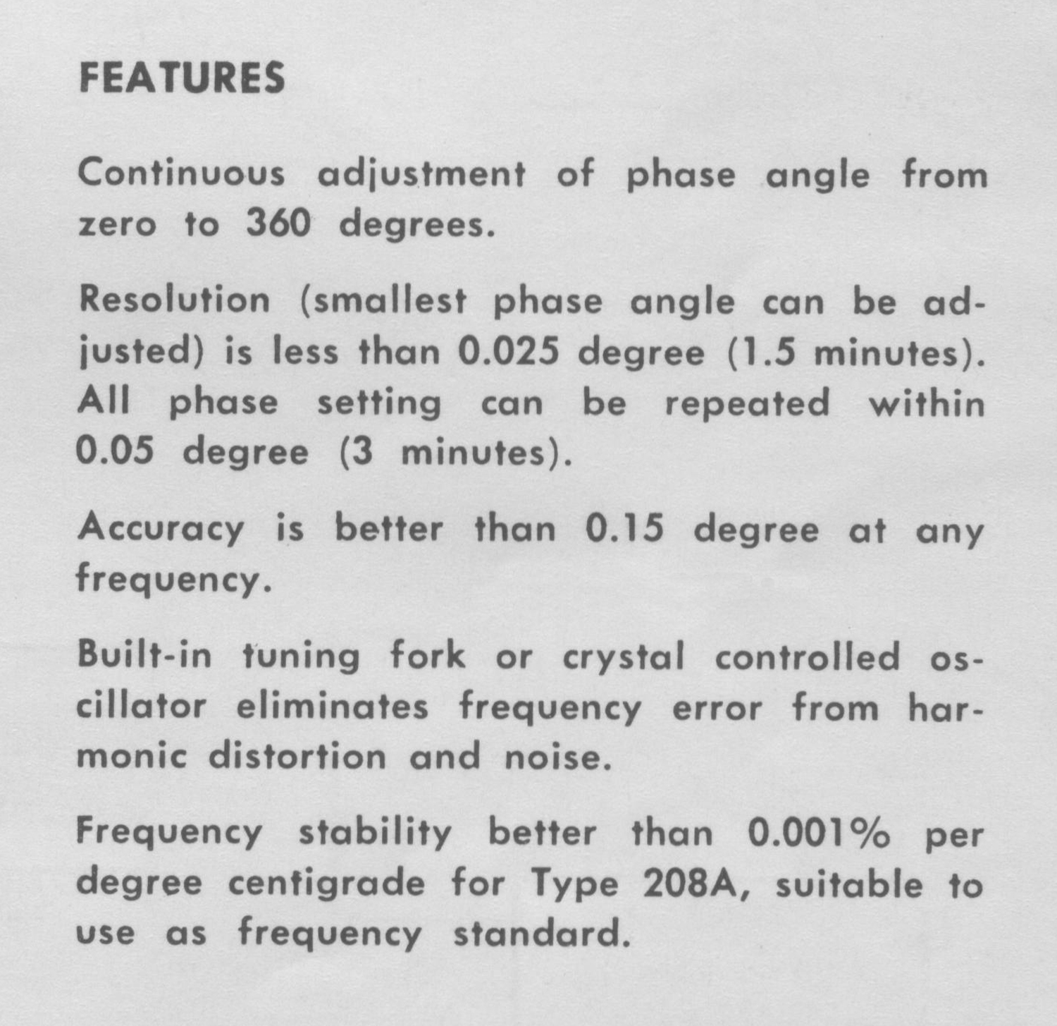
FEATURES
Continuous adjustment of phase angle from zero to 360 degrees.
Resolution (smallest phase angle can be adjusted) is less than 0.025 degree (1.5 minutes).
All phase setting can be repeated within 0.05 degree (3 minutes).
Accuracy is better than 0.15 degree at any frequency. Built-in tuning fork or crystal controlled oscillator eliminates frequency error from harmonic distortion and noise.
Frequency stability better than 0.001% per degree centigrade for Type 208A, suitable to use as frequency standard.

SPECIFICATIONS
TYPE 208 and TYPE 208A
PHASE RANGE:
0 to 360 degrees (E2 lag E1), continuously variable.
PHASE INDICATION:
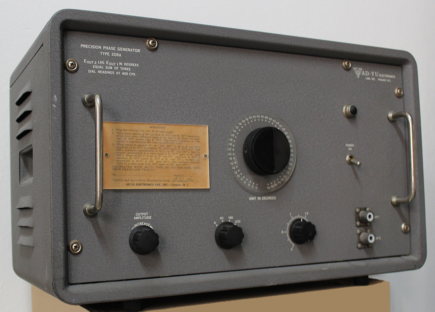
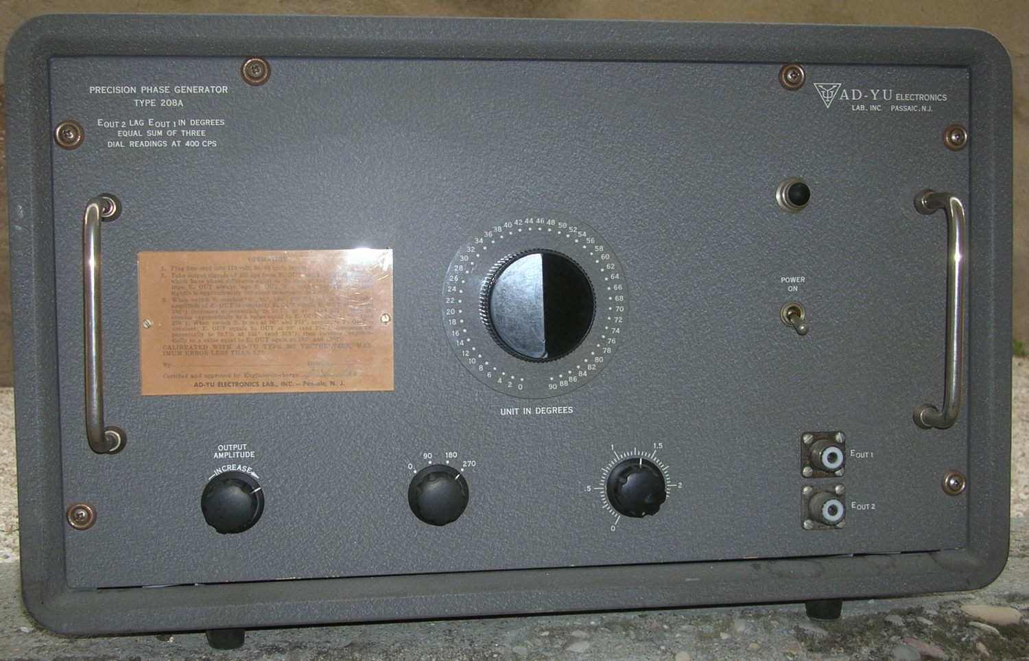
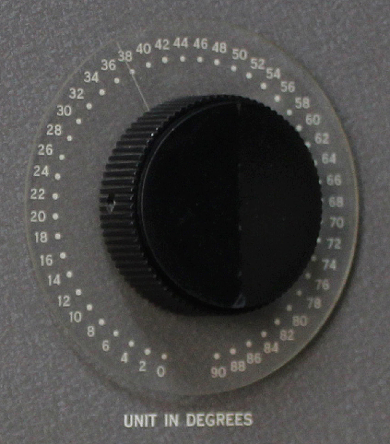
Direct reading in degrees is obtained on three dials; the first reads 0 to 270 degrees in 90 degree steps, the second reads 0 to 90 degrees in 2 degree steps, and the third dial reads 0 to 2.5 degrees in 50 divisions (0.05 degree per division), continuously adjustable.
REPEATABILITY:
Better than 0.05 degree (3 minutes) from 0 up to 360° on all three dials including the continuously adjustable dial.
RESOLUTION:
Less than 0.025 degree (1.5 minutes) increments can easily be adjusted and read from 0 up to 360° on the continuously variable dial.
FREQUENCY RANGE:
For direct phase reading, the frequency is 400 cycles or 800 cycles per second. Direct reading on any one frequency between 50 to 1500 cps
can be made on request (at slightly higher cost).
ACCURACY:
Relative accuracy 0.1 degree (6 minutes), absolute accuracy 0.15 degree
(9 minutes).
OUTPUT SIGNAL:
Type 208—Approximately equals 90% of the input signal; maximum
input
not more than 15 volts rms, variation of both E1 OUT and E2 OUT less than 3 db from 0 to 360 degrees.
Type 208A—Depends on the setting of the amplitude control,
approximately 0.05 volt minimum to 7.5 volts rms output maximum; variation of both E1 OUT and E2 OUT less than 3 db from 0 to 360 degrees.
OUTPUT IMPEDANCE:
The impedances looking into the output terminals for both E1 OUT and E2 OUT are 300 ohms nominal shunting resistance and 2 μf series capacitor for d.c. blocking.
INPUT IMPEDANCE (208 only)
1 meg shunted with 25 μμf to ground.
FREQUENCY (208A only)
Stability better than 0.001% per degree centigrade; accuracy within
0.05% at 400 cps, 800 cps, or any one frequency from 50 cps to 1500
cps (specify when ordering).
INPUT POWER:
110 volts ±10%, 50/60 cps, 40 watts (220 volts available on request).
 DIMENSIONS:
Type 208—Front panel 12”×8”; chassis 11”×7″×2½”; cabinet 14”×10”×8” deep. Type 208A—Front panel 19”x10½”, with mounting slots for standard racks; chassis 17”×8¼”×2¾”; cabinet 12”×10”×20½” (Cabinets-16-gauge, cold rolled steel, light gray wrinkle finish, rounded corners).
PRICE:
Type 208—$495.00. Type 208A-$685.00. FOB Passaic, N. J. Delivery
normally 2 to 3 weeks.
Manufactured in USA April 1962.

PHASE SHIFTER – GENERATOR TYPE 208 208A
FEATURES ● Direct reading in degrees at one frequency from 50 cps to 1000 cps, chart supplied for other frequencies . . . Type 208A has built-in tuning fork oscillator.
Specifications
FREQUENCY RANGE: Direct reading at 400 cps; any other
frequency between 50 cps to 1000 cps available on request.
PHASE INDICATION: Direct reading in degrees on 3 dials: 0-270° in 90° steps, 0-90° in 2° steps, 0-2½° continuously variable.
ACCURACY: 0.1° relative, 025° absolute.
PHASE SHIFT: Continuous phase adjustment from 0 to 360°.
MAXIMUM OUTPUT SIGNAL: Type 208—15 volts rms; Type 208A-Continuously adjustable up to 5 volts rms.
OUTPUT IMPEDANCE: 300-ohm nominal shunting resistance with 2 μf series capacitor for d.c. blocking.
INPUT IMPEDANCE: 1 meg shunted with 30 μμf to ground.
PRICE: Type 208—$445.00; Type 208A—$645.00.

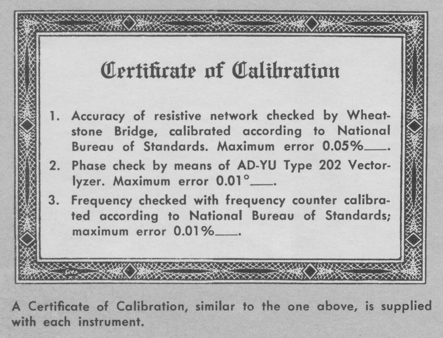
CERTIFICATE OF CALIBRATION
1. Accuracy of resistive network checked by Wheatstone Bridge, calibrated according to National Bureau of Standards. Maximum error 0.05%.
2. Phase check by means of AD-YU Type 202 Vectorlyzer. Maximum error 0.01°.
3. Frequency checked with frequency counter calibrated according to National Bureau of Standards; maximum error 0.01%».
§§§
Per consultare le altre due parti scrivere “208A” su Cerca.
Foto di Claudio Profumieri, elaborazioni e ricerche di Fabio Panfili.
Per ingrandire le immagini cliccare su di esse col tasto destro del mouse e scegliere tra le opzioni.