Precision Phase Generator type 208A AD-YU Electronics 3ª parte

Precision Phase Generator type 208A AD-YU Electronics, Lab Inc. Passaic N.J. . Terza parte.
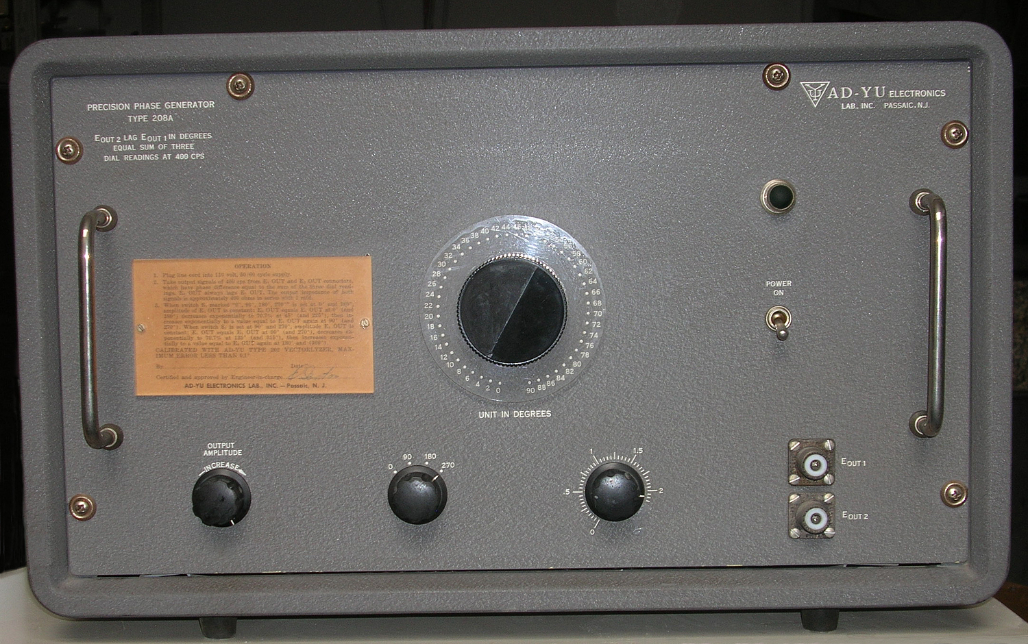
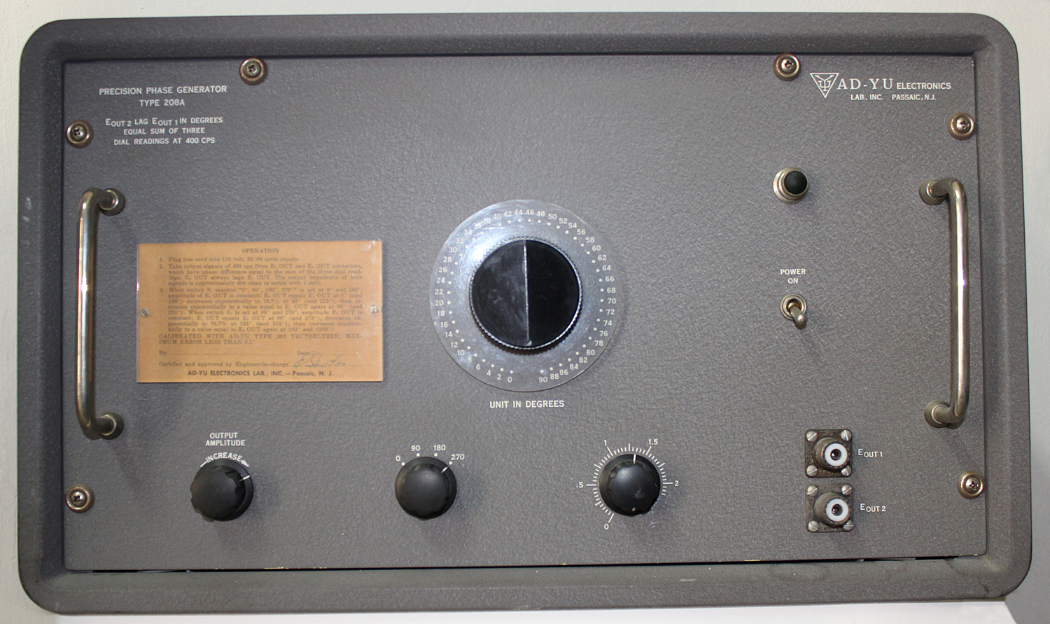
Nell’inventario D del 1956, in data  agosto 1964, al n° 3756 si legge: “Ing. MarioVianello. Milano. Circuito sfasatore “AD-YU” mod. 208A. Destinazione RAD. ₤  720.000”.
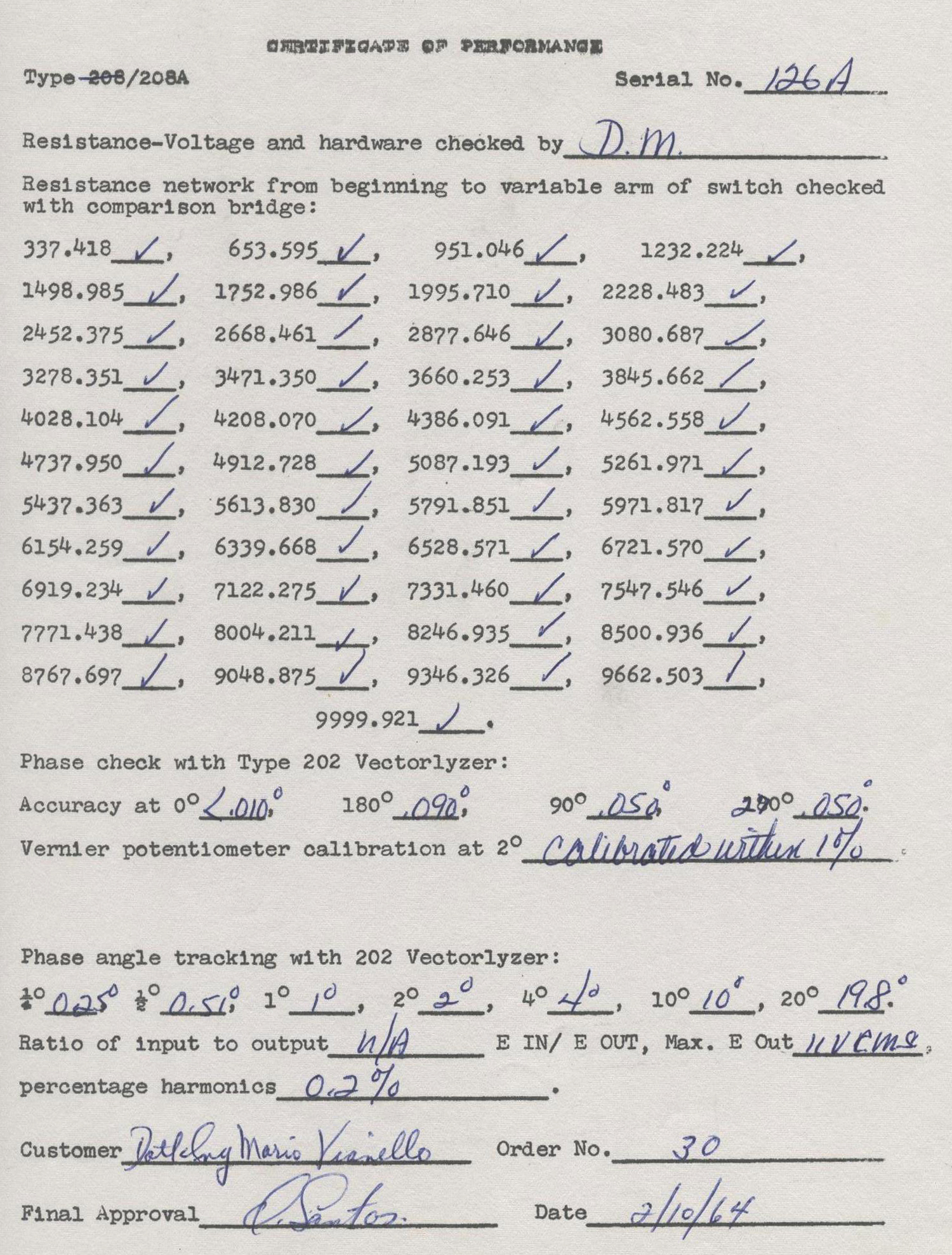
Uno scrupolo filologico sulle date si presenta quando si legge che la prova da parte del customer Dott. Ing. Mario Vianello è del 10 ottobre 1964.
Dopo aver pubblicato le prime due parti abbiamo rinvenuto ulteriori istruzioni dello strumento che abbiamo riportato qui di seguito.
§§§
Questa è la traduzione della scritta posta sulla targhetta nella parte anteriore dello strumento (vedere la prima parte).
«Dott. Ing. Mario Vianello – Milano
ISTRUZIONI PER L’USO DEL “PRECISION PHASE GENERATOR” “AD-YU” tipo 208°.
1) Collegare il cordone di alimentazione alla rete 220V, 50/60 Hz.
2) Prelevare l’uscita dei segnali di 400 Hz ai connettori E1 out E2 out, i quali hanno una differenza di fase pari alla somma delle indicazioni delle 3 manopole:
l’uscita E2 ritarda anche E1
l’impedenza dei due segnali [delle due uscite N.d.R.] è circa 400 ohm in serie ad 1 μF.
3) Quando il commutatore segnato 0°-90°-180°-270° è posizionato a 0° e 180° l’ampiezza dell’uscita E1 è costante; l’uscita E2 è uguale ad E1  a 0° e 180°, diminuisce esponenzialmente a 70,7% a 45° (e 225°), quindi aumenta esponenzialmente al valore uguale ad E1  a 90° ( e 270°).
Quando il commutatore S1 è posizionato a 90° (e 270°) l’ampiezza dell’uscita E2 è costante; l’uscita E1  è uguale ad E2  a 90° (e 270°) diminuisce esponenzialmente del 70,7% a 135° (e 315°) quindi aumenta esponenzialmente al valore di E2
a 180° (e 360°)».
§§§
Segue una nota scritta a mano: “Istruzioni più dettagliate”. Istruzioni che riportiamo qui di seguito.
§§§
« COMPLETE CIRCUIT DIAGRAM:
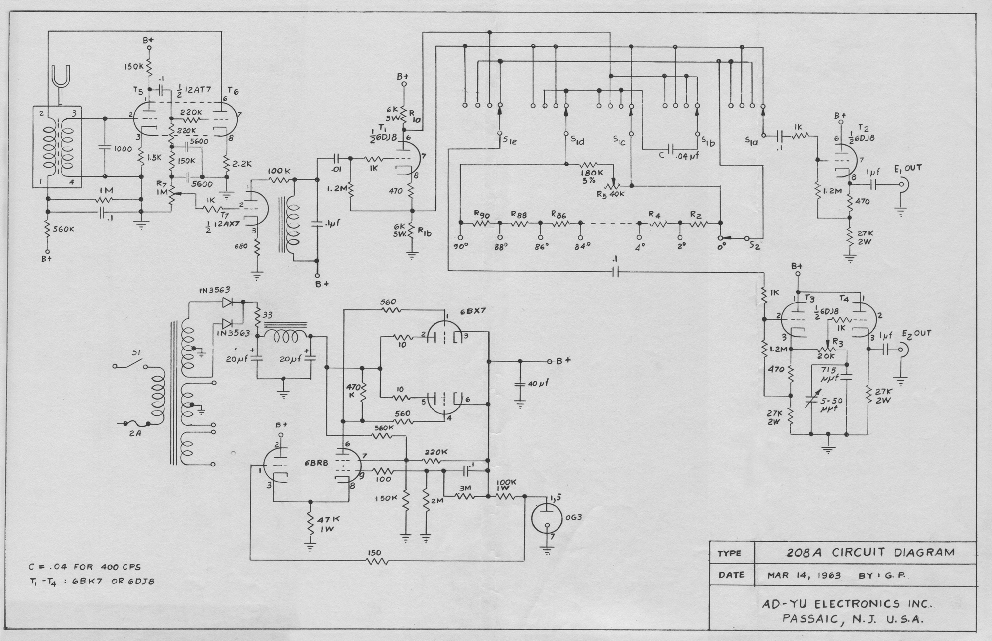
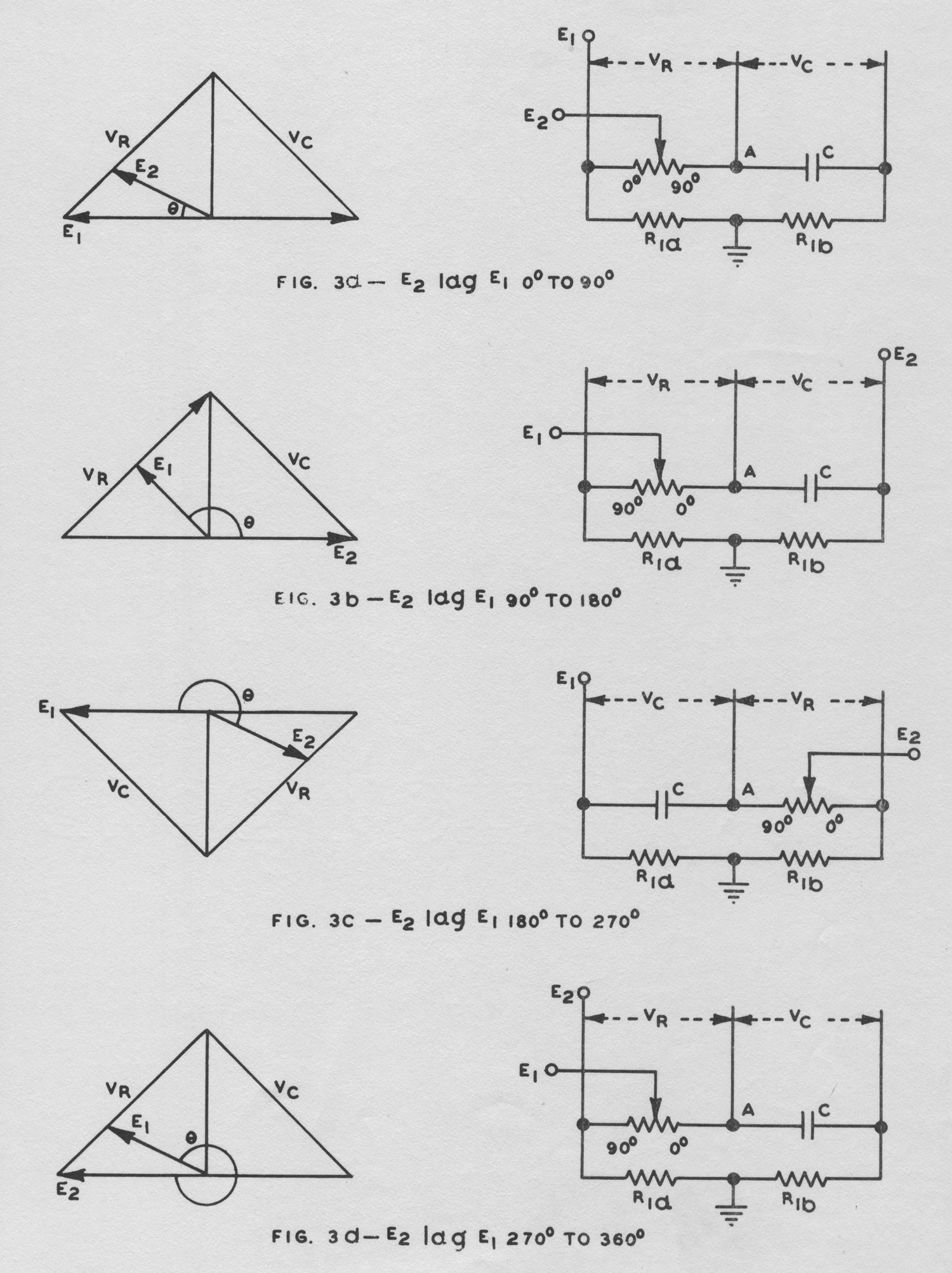
Fig. 1 shows a complete circuit diagram. T1 is used as phase inverter to provide two equal voltages with 180° phase difference when the value of R1a is exactly equal to R1b. Switch S1 has five sections and is used to alter the connections of E1 OUT, E2 OUT, as described in Figs. 3a to 3d. By adjusting R1a exactly equal to R1b, VR will be exactly equal to Vc when RWC = 1 where W = 2π × signal

Frequency [ωRC N.d.R.]. T5, T6 and T7 are used in the tuning-fork oscillator circuit of Type 208A.
PANEL CONTROLS:
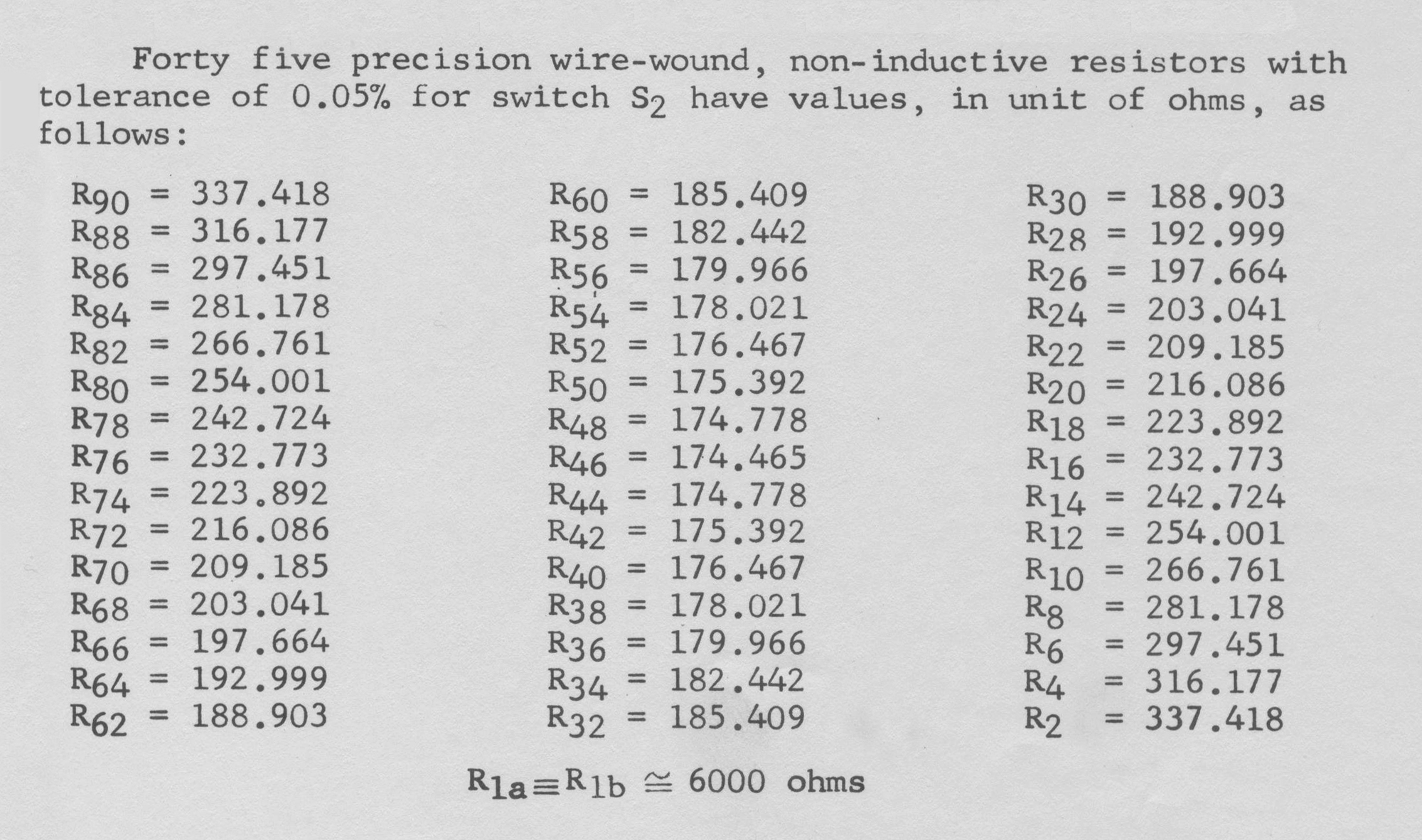
E IN – Binding post for connection of input signal (Type 208 only). 0, 90, 180, 270 degrees – Switch S1 in Fig. 1, a 5-pole, 4-position switch for providing phase shift of 0°, 90°, 180° or 270°. 0 to 90° dial – Switch S2 in Fig. 1, a 1-pole, 46-position switch for providing 0 to 90° phase shift in step of 2°. 0 to 2.5° potentiometer – Potentiometer R3 in Fig. 1, a 25K potentiometer for providing 0 to 2.5° continuous phase shift. E1 OUT, E2 OUT – Two UHF connectors for obtaining two output voltages with precision phase shift.

OUTPUT AMPLITUDE INCREASE – Potentiometer R7 in Fig. 1, a 1-meg potentiometer for adjusting the output amplitude for 0.5 volt to 10 volts rms (Type 208A only).
OPERATING PROCEDURE:
1. Plug line cord into 110 volt, 50/60 cycle supply, and apply a sine wave signal voltage with negligible harmonics and noise, not larger than 15 volts rms, to E IN binding post of Type 208. Type 208A has tuning-fork oscillator and does not require external oscillator.
2. Take output signals from E1 OUT and E2 OUT connectors. The phase shift between these two voltages is equal to the sum of the three dial readings at 400 cycles. The output impedance of both connectors is approximately 300 ohms in series with 1 μfd.
3. When the frequency of applied signal to Type 208 is slightly deviated from 400 cycles, it is suggested to use the method described under FREQUENCY VARIATION for adjusting potentiometer R5 located at the top of the chassis.
Type 208 may be used as phase shifter after the insertion phase shift of the instrument has been found with a phase meter. In this case, for 0 — 90° and 180° – 270° phase shift, take the output voltage from E2 connector.

CALIBRATION:
The accuracy of the instrument can be maintained by skillful calibration with Ad-Yu Type 202 Vectorlyzer, which has full scale sensitivity of 1°.
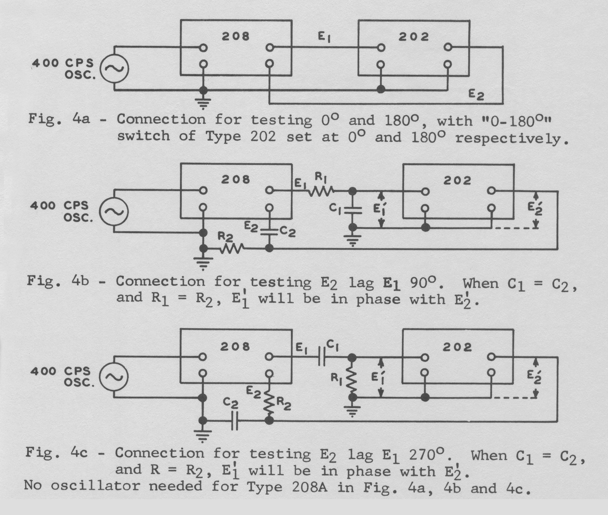
For calibration of 0°, the connection is shown in Fig. 4a. For calibration of 180°, Fig. 4a also can be used with the exception of introducing 180° phase shift in Type 202. Harmonics and hum will be added on the panel meter of Type 202, instead of cancelled out as in the case of 0°. Therefore, the signal applied to Type 208 must be
free from harmonics and noise to obtain satisfactory results. Type 208A has tuning-fork oscillator and filter for generating pure sine wave at exact frequency. For calibration of 90° and 270°, the connection is shown in Figs. 4b and 4c, respectively. Potentiometer R5 located at the top of the chassis of Type 208 or Type 208A can be adjusted in order to give 0° indication in Type 202 Vectorlyzer.
FREQUENCY VARIATION (TYPE 208 ONLY):
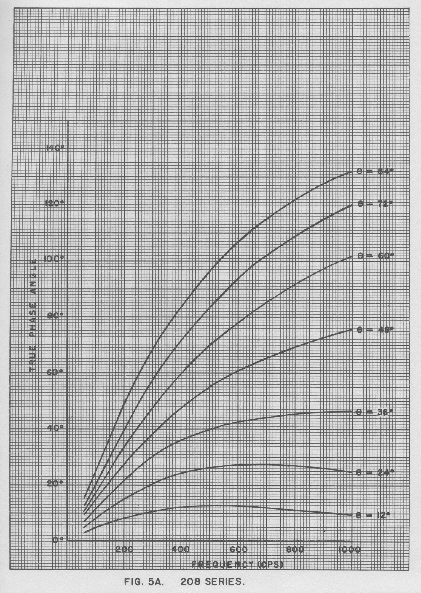
When the input signal of Type 208 is slightly deviated from 400 cycles, potentiometer R5 should be adjusted in order that RWC = 1 in Fig. 3. The arrangement in Fig. 4b can be used to test the condition of RWC = 1, at which E’1 and E’2 are exactly 90° apart, If the input signal frequency of Type 208 is far from 400 cycles and the range of potentiometer R5 is not sufficient to produce the condition RWC = 1 in Fig. 3, it is suggested to use the curves shown in Fig. 5 for correction of the dial reading. These curves show the
correct phase reading for frequency variation from 60 cycles to 1000 cycles.

VARIATION OF OUTPUT SIGNAL AMPLITUDE:
When switch S1 of Fig. 1 (0°, 90°, 180°, 270°) is set at 0° and 180° positions, the amplitude of E1 OUT is constant and the amplitude of E2 OUT varies according to Equation (1). When switch S1 is set at 90° and 270° positions, the amplitude of E2 OUT is constant and the amplitude of E1 OUT varies according to Equation (2).
(1) E2 OUT = E1 OUT/(sinθ + cosθ) for 0°-90° and 180°-270°,
(2) E1 OUT = E2 OUT/(sinθ + cosθ) for 90°-180° and 270°-360°, where θ is the dial reading of 0° to 90° dial (switch S2) only».
§§§
Per consultare le altre due parti scrivere:  “208A”  su Cerca.
Foto di Claudio Profumieri, elaborazioni e ricerche di Fabio Panfili.
Per ingrandire le immagini cliccare su di esse col tasto destro del mouse e scegliere tra le opzioni.


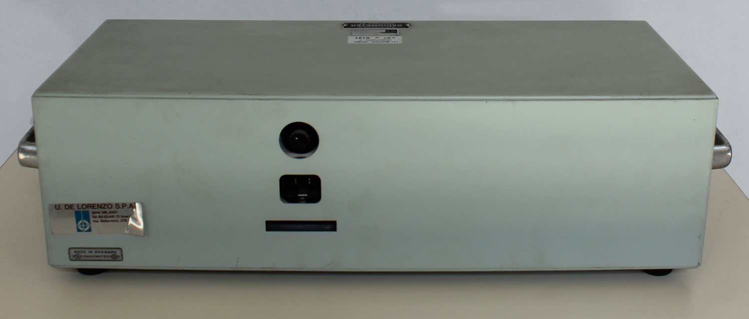
Stereo Generator Type SMG1 Radiometer Copenhagen No. 164752, 2ª parte

Type SMG1 Stereo Generator Radiometer Copenhagen No. 164752. Seconda parte.
Per ingrandire le immagini cliccare su di esse col tasto destro del mouse e scegliere tra le opzioni.
Mentre scriviamo queste note non disponiamo dell’inventario dell’epoca nel quale si trova al n° D 4932.
Dal foglio di garanzia, riportato nella prima parte, risulta la data di acquisto: 5 novembre 1970. Inoltre vi si legge che l’importatore è U. De Lorenzo s.p.a. – Milano.
Nella Sezione Elettronica è custodito il manuale di istruzioni della ditta, del quale riportiamo alcune parti.
Il testo prosegue dalla prima parte.
§§§
«
SWITCH MODULATOR
Two transistors, Q9 and Q10, are used in the switch modulator. The collectors are grounded, the bases are fed with balanced  38 kHz square-wave signals (the carrier signal), and the emitters are connected to the outputs of the input  amplifiers via a resistive network. During one half-period Q9 is saturated and Q10 is cut off, whereas Q9 is cut off and Q10 is saturated during the other half-period.
The saturated transistor leads the output signal from the corresponding input amplifier to ground via a 200 Ω resistor, producing a multiplex signal at the centre of the resistive network (the arm of  potentiometer R35). The multiplex signal from the modulator passes through a low-pass filter, which suppresses unwanted modulation products above 53 kHz.
The resistors R33 and R37 are necessary for obtaining a correct multiplex signal from the low-pass filter. A mathematical analysis shows that without R33 and R37 an MS-unbalance is present, which will cause LR crosstalk.
38 kHz CARRIER and T9 kHz PILOT SIGNAL EXCITER
76 kHz Crystal Controlled Oscillator
The 76 kHz frequency, which is basis for both the carrier and pilot signal frequencies, is crystal-controlled to secure a frequency stability better than 10-4.
The crystal operates as a series resonance circuit. The exact oscillating frequency is adjusted with an inductance, L5.
38 kHz Flip-Flop
The differentiated 76 kHz signal triggers a flip-flop, whose 38 kHz square-wave output is used as carrier signal to the switch modulator. Exactly equal half-periods of the carrier signal have been ensured by using a flip-flop triggered from a 76 kHz source.
19 kHz Flip-Flop and Low-Pass Filter
The differentiated 38 kHz square-wave triggers another flip-flop, whose output, after being filtered in a phase-stable low-pass filter, is used as the 19 kHz pilot signal. The pilot signal can be switched on or off with S101, and its level is set with a screw-driver-adjusted potentiometer R128. For synchronizing purposes it is accessible from the Sync. terminals.
PHASE-LINEAR LOW-PASS FILTER
The combined pilot and switched left/right signal passes through a 76 kHz rejector circuit to an emitter-follower Q101 .
The emitter-follower feeds a low-pass filter with extremely low phase- and amplitude-distortion up to 53 kHz to avoid MS-unbalance and consequential LR-cross-talk after decoding.
OUTPUT AMPLIFIER
The filtered signal is fed to the output amplifier, which is a 3-stage transistor amplifier with heavy feed-back in order to obtain high stability, low phase shift, low distortion and low output impedance in the frequency range 30 Hz to 75 kHz.
The SCA-Input is connected to the input of the output-amplifier through a capacitor and a resistor.
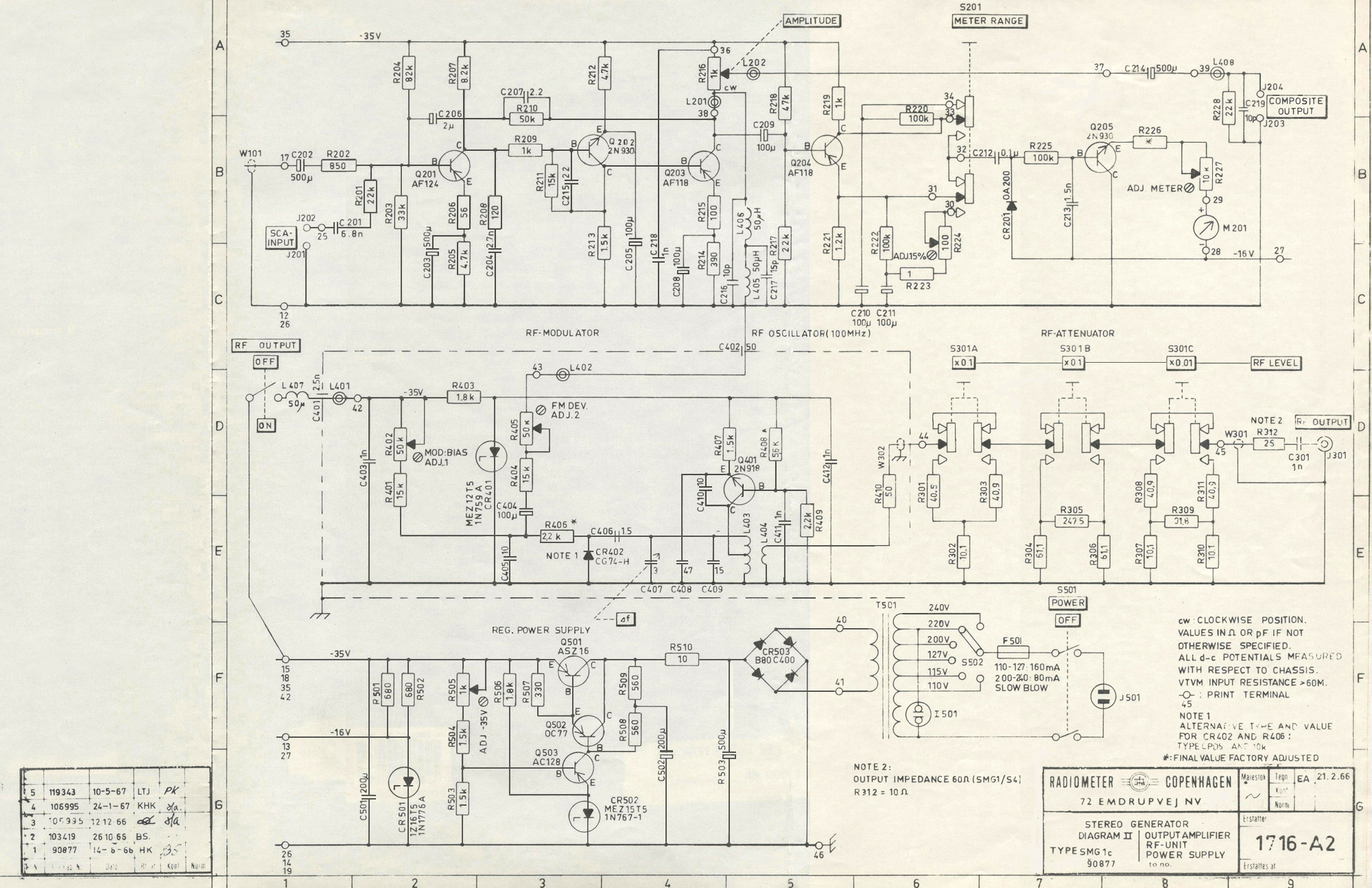
The amplifier output signal is fed to the Composite Output via a potentiometer R216 and a blocking capacitor C214.
Further, the output signal is fed to the RF-unit and to the meter circuit.
METER CIRCUIT
The meter must be peak-reading to ensure that the reading is a measure of the system  peak-deviation, when the modulation signal is a complex signal.
The meter circuit consists of the transistor Q204, the peak-rectifier CR201-C212, the dc amplifier Q205, and the meter.
With the meter range switch S201 in its normal position (range 0-100%), the transistor  Q204 will operate as an emitter-follower, supplying a very low feeding impedance to the peak-rectifier. Within the meter range 0-15%, Q204 is coupled as a common emitter with the output feeding the peak-rectifier. In this case the feeding impedance is too high to secure true peak-rectification of complex signals, so that this range should be used for measurement of the pilot signal only. If, however, this range is used for measuring a complex signal, the accuracy will be only about 5%.
The dc amplifier employs a silicon transistor Q205 with a very high current gain at small collector currents, which is necessary for true peak-rectification,
RF-UNIT
Oscillator
The 100 MHz oscillator employs transistor Q401 in a common base configuration. It has a tapped collector inductance and feed-back through capacitor C410. Small frequency changes may be made with trimmer C407, which is part of the tuning capacity.
The output is taken from a loop, coupled to the tuning inductance.
The RF-oscillator can be switched off by pulling the knob of the AMPLITUDE control.
 FM Modulator
The frequency modulator is a reactance switch modulator, CR402-C406. The part of an oscillation period during which the capacitor C406 is connected across the tuned circuit is varied in accordance with the modulation signal fed to the diode CR402. In this way a truly linear
frequency modulation is produced.
Oscillator and FM modulator are housed in a shielding box.
RF Attenuator
The RF-signal passes an attenuator having three sections of 20, 20 and 40 dB attenuation. Each section can be switched in or out, so that the output voltages from 10 μV to 100 mV are obtainable in steps of 20 dB.
The impedance level is 75 Ω. The attenuator  is protected against burn-out by a dc blocking capacitor C301. The RF-Output terminal is a type BNC connector.
REGULAT ED POWER SUPPLY
The generator can operate on the following nominal line voltages:
110, 115, 127, 200, 220, 240 volts. S502 is the line switch. The slow-blow fuse F501 protects the line transformer in case of a short-circuit.
The rectified voltage is regulated by a circuit employing three transistors and one zener diode. The regulated output voltage is set to -35 volts by the resistor R505. Some of the circuits operateon -16 volts, which are supplied via another zener diode, CR501, fed from the -35 volts supply.
The electronic regulation permits the instrument to be operated on line voltages deviating  ± 10% from the nominal value.Section G. Maintenance
GENERAL
The Stereo Generator, type SMG1, has been designed to withstand rough treatment, but careful handling and proper use assure a long life and high reliability.
Necessary repairs should be carried out only by skilled personnel, provided with the proper equipment to ensure that the repairs are correctly made.
REMOVING THE GENERATOR FROM ITS CABINET
Detach the power cord and remove the four fixing screws at the sides of the front panel. The generator can now be pulled out of its cabinet.
REPLACEMENT OF COMPONENTS
General
Print boards with the transistors soldered directly in have been used throughout in the Stereo Generator. When servicing these circuits some precautions must be taken. Use a low-power soldering iron (65 watts maximum) to avoid damaging the print boards and transistors.
Most components are directly accessible. When this is not the case, loosen the frame carrying the print board of interest by removing a few screws, and then remove the print board.
Selected Components
The transistors Q9, Q10,and Q205 have been selected. If these transistors are to be replaced, the generator should be returned  to the factory, or selected duplicates  should be ordered from the factory.
All other components may be replaced by components of equal type and tolerance.
ADJUSTMENTS
External adjustment (accessible from the front panel
1) Meter, mechanical zero.
With the power switched off, adjust the screw on the meter to meter-reading 0. Switch on the power.
2) Modulating oscillator level.
Push button SET DEV. Set the screw-driver adjustment marked LEVEL below the MODULATION FREQUENCY  buttons to full scale deflection (100%) on the meter.
3) Pilot signal level.
Push buttons MOD.OFF and PILOT.
Press button METER.
Set the screw-driver adjustment marked LEVEL below the PILOT button, so that the meter (0-15% scale) reads the required pilot level. The normalized value, 8-10%, is marked on the scale. If a pilot level greater than 15% is required, merely release the METER button and read the upper scale (0-100%).
4) RF-Unit. Frequency adjustment.
In cases where a local broadcasting transmitter interferes with the built-in 100 MHz FM-oscillator, the frequency of the latter can be shifted approx. ± 0.5 MHz from the preset value by turning the screw-driver adjustment FREQ. ADJ.
Complete Adjustment Scheme (External and Internal Adjustment)
Do not change the internal adjustments unless repairs or wear and tear make it necessary.
Before starting the adjustments, check that buttons PILOT and PRE-EMPHASIS are released.
1) Meter, mechanical zero.
With the power switched off, adjust the screw on the meter to meter-reading 0.
Switch on the power.
2) Regulated power supply. ADJ. -35 V.
Connect a dc voltmeter to the -35 volts lead. Adjust the resistor R505, marked “ADJ. -35 V”, so that the voltmeter reads -35 volts.
3) 76 kHz oscillator.
Connect an electronic counter to PILOT SYNC. terminals. Turn the inductance adjuster of the inductance L5, until the counter reads 19 kHz.
4) 76 kHz rejector circuit. “76 kHz TRAP”
Connect an oscilloscope to COMPOSITE OUTPUT terminals and synchronize from PILOT SYNC.
Push EXTERNAL MODULATION button R = L. No external modulation must be supplied.
Adjust L106 (marked “76 kHz TRAP”) to minimum vertical deflection on the scope
5) SET R = L and SET R = -L.
Push MODULATION FREQUENCY button 1 kHz.
Connect a wave analyzer, covering the frequency range up to approx. 40 kHz, to COMPOSITE OUTPUT terminals.
Push INTERNAL MODULATION button marked R = -L.
Find a residual signal close to 1 kHz with the wave analyzer.
Adjust the resistor R28 marked SET R = -L to minimum residual signal on the wave analyzer.
Push INTERNAL MODULATION button marked R = L.
Find a residual signal close to 37 or 39 kHz with the wave analyzer.
Adjust the resistor R35 marked SET R = L to minimum residual signal on the wave analyzer.
Again, push button R = -L, and repeat the procedure once or twice.
Note:
If no wave analyzer is available, the adjustment can be made in nearly the same way (but less accurately) by using an oscilloscope connected to COMPOSITE  OUTPUT terminals and synchronized from MODULATION FREQUENCY SYNC.
With R = -L button pushed, the scope will show a double side-band-signal with suppressed carrier. The presence of a 1 kHz residual signal is characterized by the fact that the tops are not situated on a horizontal line. Set R28 (marked SET R = -L) to minimum residual signal.
With R = L button pushed, the scope will show a 1 kHz sine wave with the 37 and 39 kHz residual signals superposed  as a “ripple”. Set R35 (marked
SET R = L) to minimum “ripple”.
Repeat this procedure once or twice.
6) ADJ.METER and ADJ. 15%.
Connect a vacuum-tube voltmeter to COMPOSITE OUTPUT terminals.
Turn AMPLITUDE control fully clockwise.
Push MODULATION FREQUENCY button 1 kHz.
Push button SET.DEV.
Turn the potentiometer R126, Modulation LEVEL (accessible from the front panel), until the VTVM reads 5 volts rms. .
Adjust the resistor R227, ADJ. METER, so that the built-in meter reads 100%.
Turn the potentiometer R126, Modulation LEVEL (accessible from the front panel), until the VTVM reads 0.5 volt rms.
Press METER button, and adjust the resistor R224, ADJ. 15%, until the built-in meter reads 10%.
7) MODULATION LEVEL and SET. DEV.
Push INTERNAL MODULATION button R = L.
Push MODULATION FREQUENCY button 1 kHz.
Turn the potentiometer R126, Modulation LEVEL (accessible from the front panel) until the built-in meter reads 90%.
Push button SET.DEV.
Adjust the resistor R8, ADJ. SET. DEV., so that the meter reads 100%.
Repeat the adjustment of R126 and R8 once or twice.8) PILOT LEVEL
Push buttons MOD.OFF and PILOT.
Depress button METER.
Adjust the potentiometer R128, PILOT LEVEL (accessible from the front panel), until the meter reads 8-10% (marked on the 0-15% scale).
9) PILOT PHASE
Connect an oscilloscope to COMPOSITE OUTPUT terminals, and synchronize from MODULATION FREQUENCY SYNC. terminals.
Push buttons PILOT and INTERNAL MODULATION R = -L.
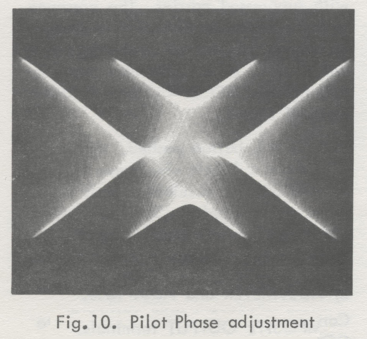
Push MODULATION FREQUENCY button  1 kHz. (If the modulation frequency by chance turns out to be a sub-harmonic of the pilot frequency, push both the 1 kHz and the 5 kHz (10 kHz for SMG1S2) buttons). Vertical as well as horizontal expansion will then produce a picture on the scope as seen in Fig. 10. Turn the inductance adjuster of the inductor L3, until the two arrow points are on the same horizontal line.
The following three items relate to the RF-UNIT. The RF-oscillator and the FM modulator are housed in a shielding box.
They are mounted on a small print board, which becomes accessible by removing four nuts and pulling away half of the box.
10) Output voltage
With all RF-LEVEL buttons out, set the output voltage to 100 millivolts by moving the loop coil L404 in relation to the tuning coil L403. Make sure that the output  voltage is correct when the cover is replaced.
Check the RF-attenuator by measuring the output voltages when the RF-LEVEL buttons are pushed in different combinations.
11) Modulation linearity and peak-deviation.
Connect an FM modulation meter (deviation meter) to the RF-OUTPUT terminal and tune it to the frequency of the RF-Unit. Connect a distortion meter or a wave analyzer to the AF-output of the modulation meter.
Push buttons SET DEV. and MODULATION FREQUENCY 1 kHz.
The meter should now read 100%.
Note:
During the following adjustments, it is important that the RF-oscillator box is assembled. Adjust with an insulated screw-driver through the holes marked
ADJ.1 and ADJ.2.
Set the resistor R402 “MOD.BlAS”(ADJ.1) to minimum modulation distortion, measured  on the distortion meter or the wave analyzer.
Set the resistor R405 “FM DEV.”(ADJ.2) to 75 kHz peak-deviation, measured on the modulation meter.
Repeat the adjustment of R402 and R405, until both potentiometers are in optimum position.
12) FREQ.ADJ. Fine-adjustment of the RF-frequency.
A fine-adjustment of the RF-frequency is made with the screw-driver adjustment FREQ.ADJ., accessible from the front panel.
The frequency change is so small that the accompanying peak-deviation change as a rule is insignificant.
If accurate peak-deviation is essential, make the adjustments outlined in 11).
DC Potentials
The potentials listed on the following pages can be used to locate faults.
The potentials  are referred to ground and measured with a vacuum-tube voltmeter with a 2 MΩ probe to avoid capacitive loading.Section H. Applications
GENERAL
This chapter does not purport to provide a complete exposition on ways and means of testing and aligning a stereo multiplex receiver or adapter. The proper procedure will to a great extent depend on what the user wants to test and which auxiliary instruments are available. In the following are sketched some measurements which can be made with the Stereo Generator and some commonly used auxiliary instruments are mentioned. With this as a guide, the user should be able to plan the measuring procedure needed for his requirements.
For use in the greater part of the measurements mentioned below, the following instruments are to be recommended:
Wave Analyzer:    Radiometer, FRA3
Audio Frequency VTVM:     Radiometer, RV24
Distortion Meter:      Radiometer, BKF6
Low Distortion Audio Oscillator:      Radiometer, HO32
Oscilloscope (without phase- or amplitude distortion for the frequency range 50 Hz -53 kHz):     Tektronix, 515
To avoid damage to your stereo generator, never apply voltages above 10 volts rms to the terminals.
INITIAL CONNECTIONS AND SETTINGS
(See also OPERATING INSTRUCTIONS).
In most cases internal modulation is adequate. Therefore, in the following, internal modulation will normally be assumed. It, however, external modulation is required, the measurements can be carried out in a similar way (see OPERATING INSTRUCTIONS).
Pre-emphasis can be used, if desired. When measuring on an adapter (or
tuner + IF amplifier + discriminator + adapter) without de-emphasis circuit (de-emphasis circuit being placed in the succeeding AF-amplifier), it is more convenient not to use pre-emphasis. In other cases it may prove more convenient to use pre-emphasis.
Note, however, that when using internal modulation and pre-emphasis, full driving signals (i.e. 100% meter deflection, 7 volts peak at COMPOSITE OUTPUT terminals with AMPLITUDE  knob turned fully clockwise, and 75 kHz peak-deviation of the RF-signal) are obtained only for 5 kHz (10 kHz for SMG1S2) modulation frequency, while lower signals are obtained for 80 Hz and 1 kHz. Full driving signals include the pilot signal.
When using external modulation and pre-emphasis, the modulating voltage should be set either to a fixed value, giving full deflection for the highest modulation frequency to be used, or it should be reduced as the modulation frequency is increased, to avoid overdriving  the Stereo Generator and thus exceeding the standard deviation.
It is assumed that the standardized pilot signal is to be used. Refer to OPERATING INSTRUCTIONS under “Special Operating Modes 2” for setting up a non-standard pilot amplitude or phase.
Some of the following measurements are not exclusively applicable to stereophonic investigations, but can also be used in work on monophonic  FM receivers (or stereophonic receivers operated as monophonic receivers). In such cases, always push R = L (M) button (INTERNAL or EXTERNAL MODULATION), and release PILOT button. Except for this, proceed as described in the following.
The initial connections and settings depend on which output signal is to be used – i.e. the composite output for adapters or the RF-output  for receivers.
Initial connections and settings for measurements on adapters
1) Connect the adapter to COMPOSITE OUTPUT terminals.
2) Push button PILOT.
3) Push the appropriate PRE-EMPHASIS button (European standard: 50 μsec, American standard: 75 μsec), if desired.
4) Push 1 kHz MODULATION FREQUENCY button.
5) Set AMPLITUDE KNOB to the level suitable for the adapter. This can be accomplished in several ways:
Push one of the INTERNAL MODULATION BUTTONS.  With an oscilloscope connected across  COMPOSITE OUTPUT terminals, the peak-to-peak value can be measured on the screen.
Using a normal rms-calibrated vacuum voltmeter, the signal used for setting the level must be a pure sine-wave. This can be obtained by pushing  SET DEV. button.
A conventional VTVM (rms-calibrated, mean-value or rms-measuring) should be used only for purposes of comparing.
When the built-in meter reads 100% and AMPLITUDE control is turned fully clockwise, the peak-voltage on COMPOSITE OUTPUT terminals will be close to 7 volts. By now comparing the readings of a VTVM connected across COMPOSITE OUTPUT terminals, when AMPLITUDE knob is turned fully clockwise, with the readings when it is turned partly up, it is possible to calculate the peak output voltage for any AMPLITUDE setting.
The stereo generator is now ready for the measurements on adapters described in the following paragraphs.Initial connections and settings for measurements on receivers
1) Push the RF-oscillator switch (knob of the AMPLITUDE control).
2) Set RF-LEVEL to an appropriate value.
3) Push PILOT button.
4) Push appropriate PRE-EMPHASIS button (European standard: 50 μsec, American standard: 75 μsec), if desired.
5) Push 1 kHz MODULATION FREQUENCY button.
6) Connect RF-OUTPUT terminals to the antenna terminals of the receiver, and tune the receiver to the output frequency of the stereo generator (approx. 100 MHz)
The stereo generator is now ready for the measurements on receivers described in the following paragraphs.
LR SEPARATION (LR-SEPARATION IS EQUAL to MS-IDENTITY)
1) Push button L.
2) Measure the voltages at the left and right output terminals of the adapter or receiver. The ratio of these voltages is the L to R separation (L to R crosstalk).
3) Push button R.
4) Measure the voltages at the right and left output terminals of the adapter or receiver. The ratio of these voltages is the R to L separation (R to L crosstalk).
5) If desired, repeat the measurements for other modulation frequencies.
Note:
In case the output signal of the adapter or receiver contains hum, or 19 or 38 kHz residual signals, make sure that these signals do not compromise the measurements. Use a selective vacuum tube voltmeter (wave analyzer), appropriate filters in front of a VTVM, or an oscilloscope synchronized from the MODULATION FREQUENCY SYNC. LR BALANCE EXPRESSED BY MEANS OF THE IDENTITY FACTOR (LR-IDENTITY IS EQUAL TO MS-SEPARATION)
The identity factor is an expression of the differences in amplification of L- and R-channels.
Let the ratio of the amplification of L-channel to that of R-channel be denoted by “f”, then the Identity Factor is equal to

20 log10  (1+f)/(1-f) dB.

Measuring the Identity Factor
1) Connect the ungrounded side of the L and R output terminals of your adapter or receiver through two identical resistors in series. The value of the resistors must be high as compared with the output impedance of your adapter or receiver.
2) Press button R = L (M)
3) Measure the voltage between the point of junction of the two resistors and ground (V1) by means of a frequency analyzer (or a VTVM and a low-pass filter which removes any residual signals that may be present at 19 kHz and 38 kHz).
4) Press button R = -L  (S).
5) Measure the resultant voltage (V2).
The LR identity factor can now be determined as

20 log  V1/V2 dB.

FIDELITY
If a check of the fidelitypat the three built-in modulation frequencies is sufficient:
1) Push button L.
2) Measure the voltage on the left output terminals  of the adapter or receiver for modulation frequencies 1 kHz, 80 Hz and 5 kHz. (80 Hz, 1 kHz or 10 kHz for SMG1S2.)
If the de-emphasis of the adapter or receiver agrees with the pre-emphasis of the Stereo Generator, the voltage will be the same for all three modulation frequencies, when the tone controls are in neutral position.
3) Repeat the measurement for the right channel by pushing R ONLY button and measuring on the right output terminals of the adapter or receiver.
If a detailed frequency response is to be measured:
1) Push L & R button (EXTERNAL MODULATION).
2) Connect an external audio signal generator  to L INPUT terminals, and adjust its output voltage to full deflection on the meter for the highest modulation frequency to be used.
3) Measure the voltage on the left output terminals of the adapter or receiver as a function of frequency. If the de-emphasis of the adapter agrees with the pre-emphasis of the Stereo Generator, the voltage will be frequency-independent in the audio frequency range, when the tone controls are in neutral position.
4) Connect the audio signal generator to R INPUT terminals and repeat the measurement of the right channel.
Measuring the frequency response for the monophonic (M) channel and the stereophonic (S) sub-channel
1) Push button R = L (M) (INTERNAL or EXTERNAL MODULATION, as required).
2) Measure the voltage on the left or right output terminals of the adapter or receiver as a function of frequency.
3) Push button R = -L (S), and repeat the measurement.
DISTORTION
In most practical cases it is sufficient to check the distortion at a low, a medium and a high modulation frequency. The built-in modulating oscillator is designed with due regard to this particular application. Its distortion is very low, its low modulation frequency has been chosen so as not to interfere with the line frequency, and its high modulation frequency has been selected as the maximum frequency, whose second and third harmonics will pass through the AF amplifier of the receiver under test.
If other test-frequencies are required, a low-distortion, audio frequency signal generator should be used.
Measuring  the distortion
1) Push one of the modulation buttons of FUNCTION SELECTOR, depending on the type of multiplex-signal for which the distortion is to be measured.
2) Measure the distortion with a wave analyzer or a distortion meter connected to that adapter – or receiver – output that corresponds to the type of multiplex-signal under measurement.
3) If desired, repeat the measurement for modulation frequencies of 80 Hz and 5 kHz, (10 kHz for SMG1S2), and for other types of multiplex-signals.
Note:
If a distortion meter is used, make sure that the measurements are not disturbed by 19 or 38 kHz spurious signals. If that is the case, insert a low-pass filter with a cut-off frequency of 15 kHz (and, perhaps, traps at 19 and 38 kHz) in front of the distortion meter.
MEASURING INTERMODULATION BETWEEN THE HARMONICS OF THE L OR R SIGNAL AND SIGNALS AT 19 kHz AND 38 kHz (THE PILOT SIGNAL AND THE REGENERATED CARRIER SIGNAL)
Components produced by intermodulation of this kind in the stereo generator are typically 90-100 dB below the level of the L or R signal.
Measuring intermodulation with an R or L signal frequency, fA:
1) Connect a low-distortion generator to the L or R input (the built-in modulation generator can be used, too).
2) Push button R & L.
3) Set the frequency of the signal generator to fA, and adjust the amplitude, so that the built-in meter reads 100%.
4) Measure the intermodulation components at the output of either channel by means of a frequency analyzer. The frequency of the intermodulation components will be

±n1 × fA ± n2 × 19 kHz,

where n1 and n2 are integers.
M AND S CHANNEL  IDENTITY OF TUNER, IF AMPLIFIER AND DISCRIMINATOR IN A RECEIVER (MS- IDENTITY  IS EQUAL TO LR -SEPARATION)
Measured with an oscilloscope
1) Connect an oscilloscope to the discriminator output. Make sure that the capacitive load gives a cut-off frequency that is larger than 500 kHz. Do not use a probe, as this will cause amplitude- and phase-distortion, it not adjusted very carefully.
Trigger the oscilloscope from MODULATION FREQUENCY SYNC. terminal.
Use an oscilloscope with a flat amplitude and a linear phase characteristic from 30 Hz to at least 75 kHz. 2) Push L or R button.
3) Release PILOT button.
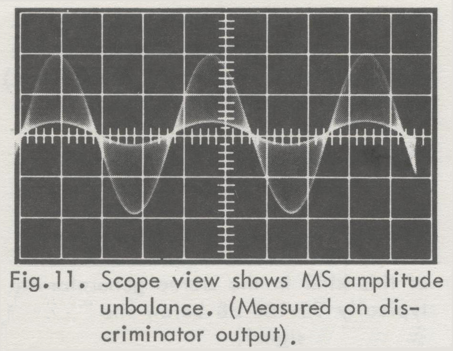
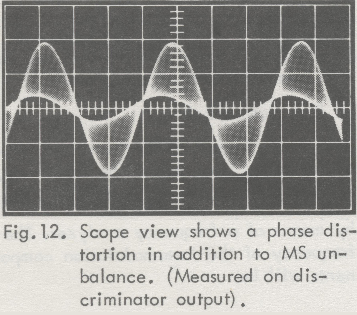
4) The scope will now show a picture as in Fig. 11 or 12.
Fig. 13 shows the ideal case with perfect M and S channel identity. In practice, however, scope views as in Fig. 11 and 12 will be obtained.
Fig. 11 shows MS amplitude unbalance (the S channel amplitude is too low). From this picture the MS Identity Factor equal to the LR Separation (after demodulation in an ideal multiplex decoder) can be calculated as shown in Fig. 14.
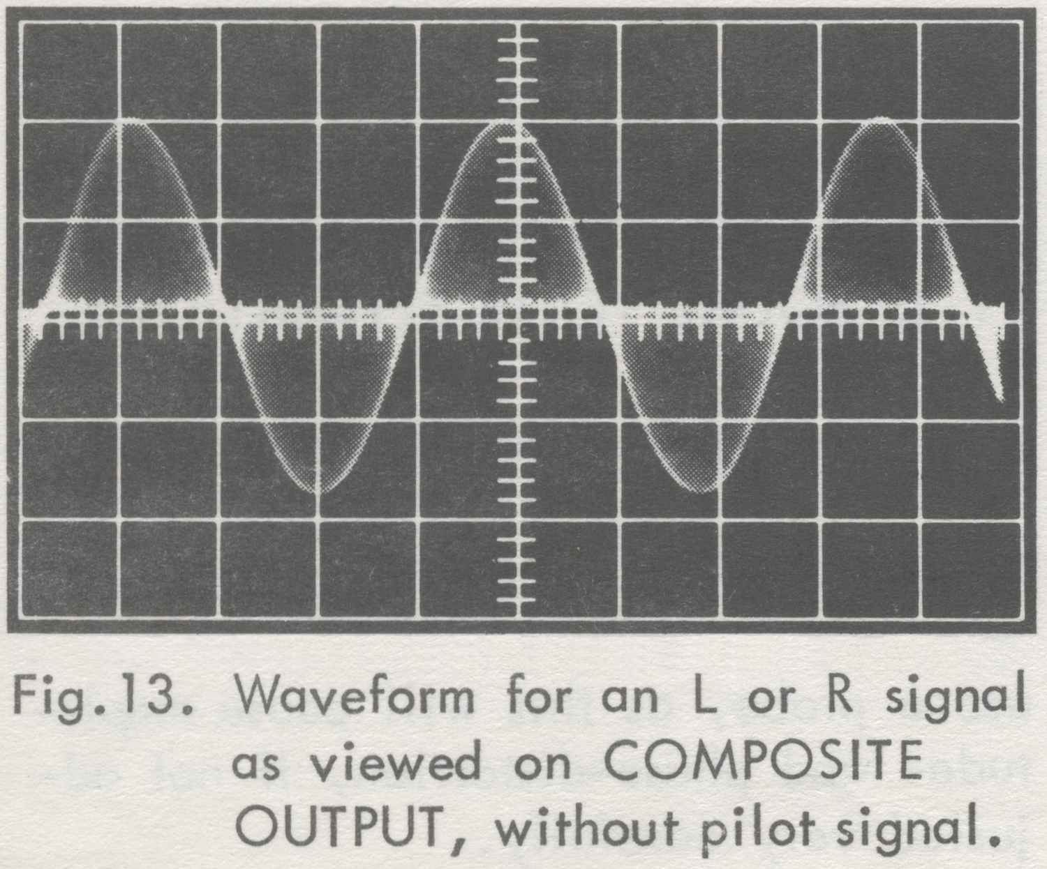
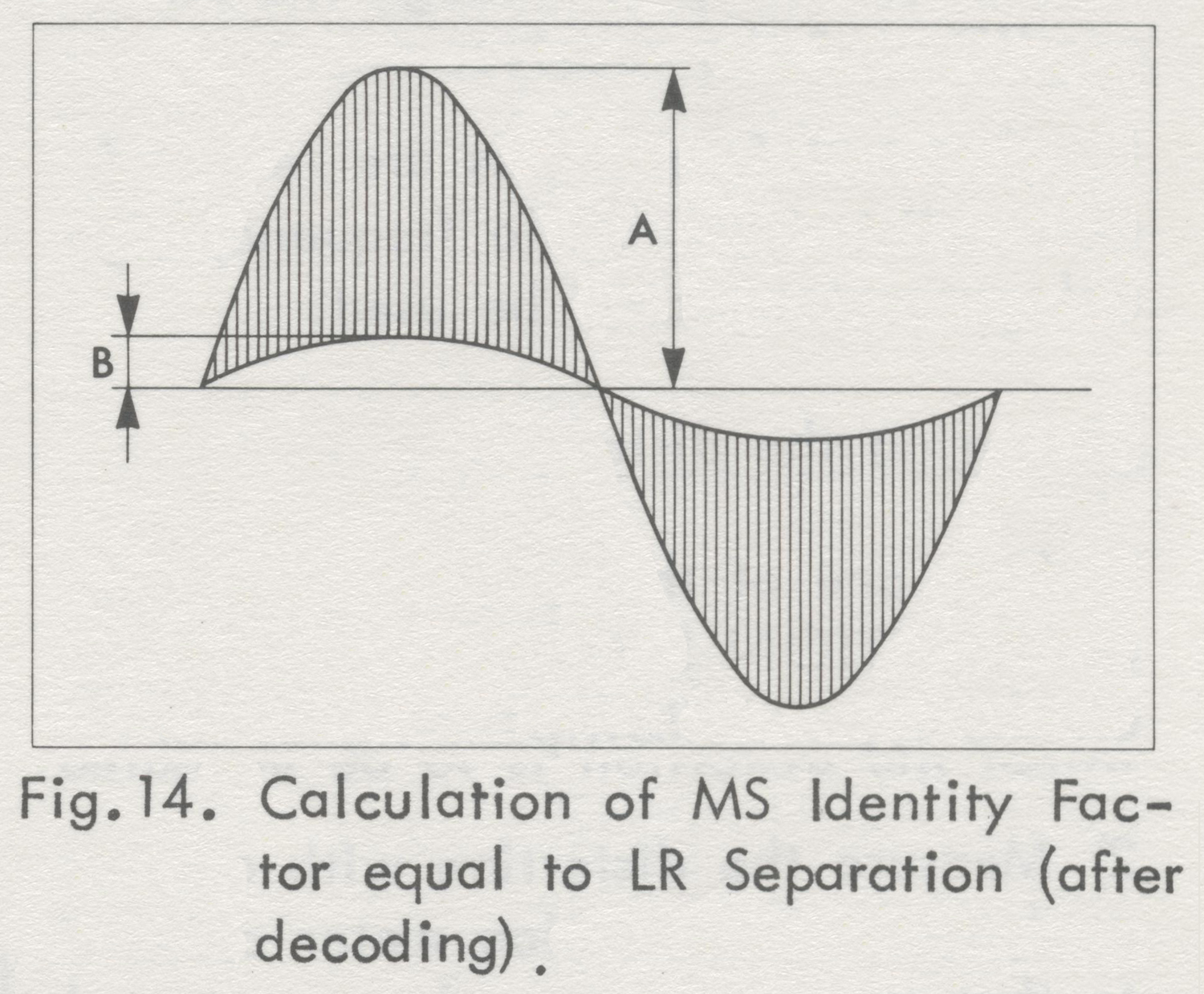
Fig. 12 shows a phase distortion in addition to MS amplitude unbalance (indicated by a non-coincidence of corresponding tops of the two sinusoidal envelopes).
5) Repeat the measurement for other modulation frequencies; if convenient, also for a very high frequency (10 to 15 kHz, using external modulation),  where MS unbalance and especially phase distortion
often are very pronounced.
Measured with a wave analyzer (for frequencies up to 53 kHz)
(This method gives no information aboutphase distortion).
1) Connect a wave analyzer to the discriminator output. Make sure that the capacitive load gives a cut-off frequency that is larger than 500 kHz.
2) Push L or R button
3) Measure the discriminator output signal components at the modulation frequency (monophonic  channel), and at 38 kHz plus and minus the modulation frequency (stereophonic sub-channel sidebands) .
For perfect MS identity the amplitude of the two sidebands should be equal, and either should be equal to half the amplitude of the monophonic channel signal.
If phase distortion is disregarded, the MS Identity Factor will be:

20 log10  (1+f)/(1-f) dB,

f = m/(s1 + s2)

where m is the monophonic channel signal voltage, and s1 and s2 are the voltages of the stereophonic sub-channel side-bands.
M AND S CHANNEL SEPARATION OF TUNER, IF AMPLIFIER AND DISCRIMINATOR OF A RECEIVER (MS-SEPARATION IS EQUAL TO LR-IDENTITY)
M to S Separation (Crosstalk)
1) Connect a wave analyzer (frequency range: 40 Hz to 53 kHz) to the discriminator output.
2) Push button R = – L (M)
3) Measure the discriminator output signal components at the modulation frequency (monophonic  channel), and at 38 kHz plus and minus the modulation frequency (stereophonic sub-channel sidebands) .
The M to S separation is:

20 log10 m/(s1 + s2) dB,

where m is the monophonic channel signal voltage, and s and s are the voltages, and s1 and s2 are the voltages of the  (unwanted) stereophonic sub-channel sidebands.
S to M Separation (Crosstalk)
1) Connect a wave analyzer (frequency range: 40 Hz to 53 kHz) to the discriminator output.
2) Push button R = -L (S).
3) Measure the discriminator output signal components at the modulation frequency (monophonic channel), and at 38 kHz plus and minus the modulation frequency (stereophonic sub-channel sidebands).
The S to M separation is:

20 log10 (s1 + s2)/m dB,

where m is the voltage of the (unwanted) monophonic channel signal, and s1 and s2 are the voltages of the stereophonic sub-channel sidebands.
PILOT RESERVE
A stereophonic FM-receiver should in all circumstances be able to function correctly, even if the pilot sub-carrier were to depart from its normal level.
A deviation from the optimal value of amplification in tuners, etc., may very likely be caused by aging.
Measuring Pilot Reserve
1) Push button L (the R-channel could be used as well).
2) Reduce the level of the pilot signal until minimum allowable L to R separation, or maximum allowable distortion of the L channel, is reached.
Measuring the separation and measuring the distortion are described above.
The level of the pilot signal is changed by turning screwdriver adjustment LEVEL below button PILOT.
3) Push button MOD. OFF.
4) Read the level of the pilot signal on the meter. Press button METER to get an accurate reading.
5) Push button L.
6) Increase the level of the pilot signal until minimum allowable L to R separation or maximum allowable distortion is reached. However, the pilot signal should not exceed the level corresponding to 20% modulation.
7) Push button MOD. OFF.
8) Read the level of the pilot signal on the meter.
9) The readings in (4) and (8) give the allowable range of the pilot signal amplitude.
Note:
The measurements at increased pilot signal level assume that the FM- receiver has a bandwidth large enough not to cause distortion for a 10% increase of the frequency deviation.
MEASURING FM DISCRIMINATOR CHARACTERISTICS
In multiplex stereo development work it often may be necessary to measure the harmonic distortion of the FM discriminator versus the modulation frequency. The modulation frequency range is 40 Hz to 53 kHz. If an FM signal generator capable of handling this modulation frequency range is not available, the Stereo Generator can be used.
See OPERATING INSTRUCTIONS for further instructions.
For the distortion measurements use a wave analyzer, accepting high frequencies (up to third harmonic of the highest modulation frequency), or use a VLF receiver (20 – 200 kHz) or appropriate filters together with a wide-band VTVM.
LISTENING TESTS
1) Connect a gramophone or tape recorder to the AUDIO INPUT.
2) Push buttons AUDIO, PILOT and PRE-EMPHASIS (European Standard: 50 µsec, American Standard: 75 µsec).
3) Turn SENSITIVITY knob, so that the meter reads 50-70% during loud passages in the music.
Note:
During interruptions or soft passages in the sound, the tone of the built-in oscillator may be heard. To eliminate this tone, the oscillations of the built-in oscillator should be stopped by releasing all three frequency buttons of the oscillator. All three buttons are released by gently pushing one of the buttons just so far that the other two buttons are released, and then letting go of the button».
§§§
Per consultare la prima parte scrivere ”SGM1” su Cerca.
 Foto di Claudio Profumieri; elaborazioni, ricerche e testo a cura di Fabio Panfili.


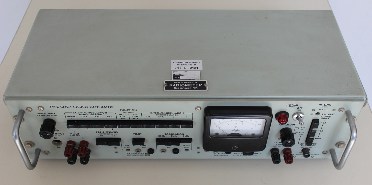
Stereo Generator Type SMG1 Radiometer Copenhagen No. 164752, 1ª parte

Type SMG1 Stereo Generator Radiometer Copenhagen No. 164752. Prima parte.
Per ingrandire le immagini cliccare su di esse col tasto destro del mouse e scegliere tra le opzioni.

 Mentre scriviamo queste note non disponiamo dell’inventario dell’epoca nel quale lo strumento si trova al n° D 4932.Dal foglio di garanzia risulta la data di acquisto: 5 novembre 1970. Inoltre vi si legge che l’importatore è U. De Lorenzo s.p.a. – Milano.
Nella Sezione Elettronica è custodito il manuale di istruzioni della ditta, del quale riportiamo alcune parti.
§§§

«Stereo Generator Type SMG1
Section A.  Introduction
PRINCIPLES FOR GENERATING A MULTIPLEX STEREO-SIGNAL ACCORDING TO THE FCC SYSTEM
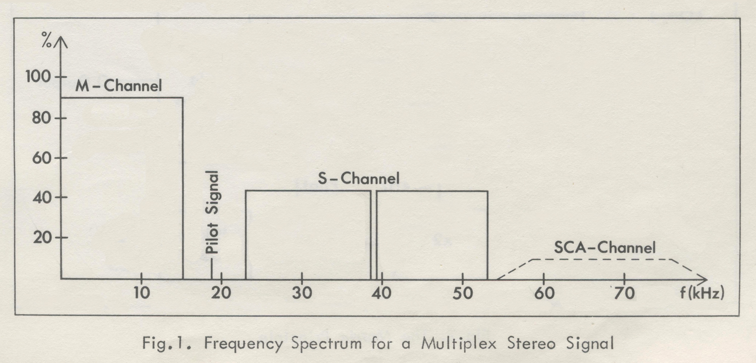
The frequency spectrum for a multiplex Stereo-signal of the approved FCC system is shown in Fig.1.

The M-channel (Main or Monophonic Channel) occupies the frequency range 50 Hz to 15 kHz. The M-signal is made up of the sum of the left and right  signals (L + R). This enables a stereophonic broadcasting station to be received on a monophonic receiver (compatibility).
The difference between the left and right signals (L – R) is transmitted as a double sideband signal, amplitude-modulated on a suppressed sub-carrier of 38 kHz  (S-channel or stereophonic sub-channel, covering the frequency range 23 – 53 kHz).
In the receiver, the difference signal (L – R) is obtained by regenerating the 38 kHz carrier and demodulating  the S-channel.
However, this carrier must be in exact phase with the suppressed 38 kHz carrier on the transmitter side, and to accomplish this, a pilot signal of 19 kHz (half of the suppressed carrier frequency) is transmitted with a normalized amplitude and with a stated phase relationship to the suppressed carrier.
The FCC allows a third channel, the SCA-channel (Subsidiary Communications  Authorization) to be transmitted as a frequency-modulated sub-carrier on 67 kHz. This channel is used for background music in department stores, etc. It must not occupy more than 10% of the maximum peak- deviation of the FM broadcast transmitter.
The multiplex stereo signal can be generated in the two ways described in the  following:
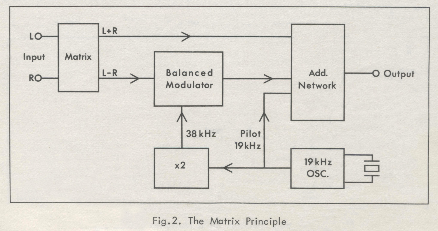
Fig.2  shows the Matrix Principle. In a matrix circuit the sum (L+ R) and the difference (L – R) of the left (L) and right (R) signals are obtained. The sum- signal is passed onwards to an adder network, and the difference-signal is modulated  into a 38 kHz carrier. Using a balanced modulator, the carrier is suppressed, so that the modulating process results in two sidebands, which pass on to the adder network.
The 38 kHz carrier is obtained by  frequency-doubling a 19 kHz signal from a crystal-controlled oscillator.  The 19 kHz signal is also fed to the adder network as a pilot signal.The output signal from the adder network is the composite multiplex stereo-signal, which is used to frequency-modulate the transmitter.
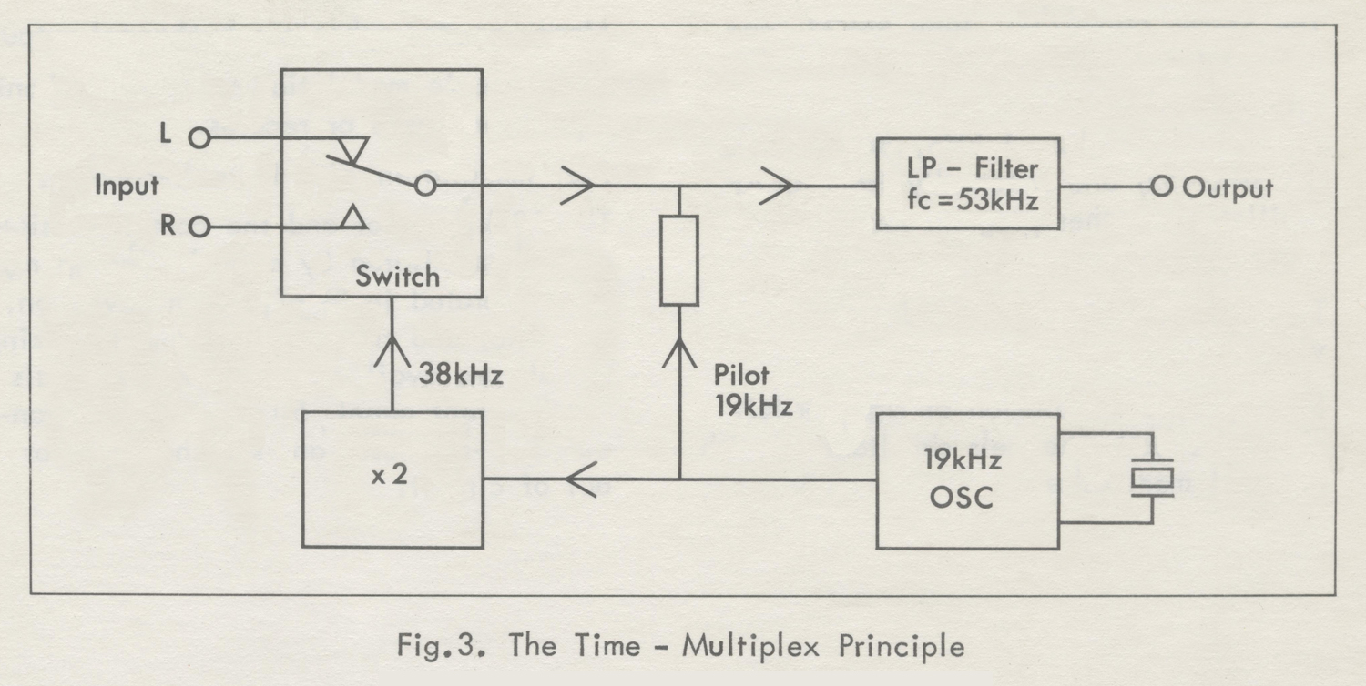
Fig.3  shows the Time-Multiplex or Time- Division Principle.  Here an electronic switch alternates between the left (L) and right (R) signal at a frequency of 38 kHz.
The 38 kHz carrier and the 19 kHz pilot signal are formed in the same way as in the Matrix Principle.
By the switching process, sidebands to the odd harmonics of the carrier frequency  will be produced. They are, however, eliminated by a filter with a 53 kHz cut-off frequency.Mathematically it can be proved that the output-signal from the filter has the frequency spectrum shown in Fig.1, except that some unbalance between the main-channel and the stereophonic sub-channel is present. This unbalance would result in LR cross-talk after decoding; however,
the unbalance can be compensated for either in the switching modulator or in the filter.
THE STEREO GENERATOR, TYPE SMG1
In the Stereo Generator, type SMG1, the time-multiplex principle has been adopted, because of its obvious advantages, of which one of the most  significant is the completely uniform handling of the left and right signals, which implies that minor amplitude – and phase – differences become less probable.
The Stereo Generator, type SMGT, is a transistorized, line-operated instrument that complies with the standards for stereophonic broadcasting approved by the American FCC and recommended by the
European Broadcasting Union (EBU).
The composite signal may be used testing stereo adapters or driving FM
generators to a full 75 kHz deviation.
A built-in 100 MHz oscillator, frequency-modulated by the composite
signal and provided with a step attenuator, makes the instrument self-contained by generating an FM multiplex signal for tests on receivers and tuners.

The Stereo Generator, type SMG1, can be modulated internally by a built-in oscillator with choice of 80 Hz, 1 kHz, and 5 kHz (80 Hz, 1 kHz, and 10 kHz for SMG1S2) and externally from an AF oscillator or other program source.
The following operating modes are provided:
Stereophonic modulation of right or left channels. Both channels simultaneous with external modulation.
Mono-or stereophonic sub-channel output.
Stereophonic modulation with stereophonic input  from tapes or records.
SCA modulation with FM sub-carriers.
The 19 kHz pilot and the composite signal are monitored by a peak-reading meter calibrated in % of system deviation.
The pilot and the oscillator synchronizing signals are available from two terminals on the front panel. 50 and 75 μsec. standard pre-emphases are switchable in or out of circuit.
Section B. Specifications
INPUTS
Left (L) and Right (R) Inputs
Frequency range: 40 Hz to 15 kHz.
Fidelity:  ±0.2 dB.
Input Voltage:  Approx. 250 millivolts  rms for 100% modulation (inclusive of 10% pilot signal). Maximum input voltage is 10 volts.
Input Impedance: 10 to 15 KΩ depending on FUNCTION SELECTOR  setting.
Audio Input  (Provides for stereo inputs from tapes and records. An input filter suppresses 19 kHz spurious signals).
Frequency Range: 40 Hz to 15 kHz,
Fidelity:  Approx.  ±1 dB up to 12 kHz.
Input Voltage: Approx. 250 millivolts to 10 volts rms for 100% modulation (inclusive of 10% pilot signal), depending on SENSITIVITY setting.
Input Impedance: Approx. 15 kΩ .
SCA Input    (Subsidiary Communications Authorization.
Frequency Range: 10 to 75 kHz,
Fidelity: ±0.5 dB.
Input Voltage: Approx. 250 millivolts rms for 10% modulation.
Input Impedance: 22 kΩ .
MODULATING OSCILLATOR
Frequencies  80 Hz, 1 kHz and 5 kHz.
Accuracy  ± 5%,
Distortion Less than 0.1%.
PRE-EMPHASIS Standard 50 μsec pre-emphasis ± 1 dB.
Standard 75 μsec pre-emphasis ± 2 dB.
Switchable in or out of circuit.
OPERATING MODES
External Modulation
AUDIO    Provides for stereo inputs from tapes and records tor listening tests.
L & R   Normal two-channel multiplex signal output (also left only or right only signals).
R = L     Monophonic channel output.
R = -L   Stereophonic sub-channel output.
Internal Modulation
R = L    Monophonic channel output.
R = -L  Stereophonic sub-channel output.
L           Left channel multiplex signal output.
R          Right channel multiplex signal output.
Modulation OFF    No modulating signal supplied, only 19 kHz
pilot supplied by pressing PILOT push-button.Set Deviation   Pure sine-wave output supplied from COMPOSITE OUTPUT for setting deviation of external RF FM signal generator, it used.
OUTPUTS
Composite Output
Level:  0 to 7 volts peak.
Load Impedance:   Minimum 1500 Ω shunted by maximum 300 pF
Overdrive Limit:     Approx. 10 volts peak for load impedances greater than 10 kΩ.
Output Impedance:   40 to 250 Ω, depending on AMPLITUDE setting.
Distortion:   Less than 0.2%.
Residual Hum and Noise:   Less than 0.03%.
Residual 38 kHz Carrier:     less than 1%, typically  0.5%.
Residual Spurious Signals above 53 kHz:   Approx. 1%.
Pilot Signal:   Switchable in and out.
Pilot Frequency:   19 kHz  ± 2 Hz,
Pilot Level:   Adjustable from 0 to 20%.
LR Separation:   Better than 40 dB. Typically 45 dB modulation frequencies below 10 kHz.
MS  Separation:
(Except AUDIO INPUT)
Pre-emphasis out: better than 45 dB.
Pre-emphasis in: better than 40 dB.
Modulating Oscillator Sync. Output
Frequencies:     80 Hz, 1 kHz and 5 kHz. (80 Hz, 1 kHz and 10 kHz for SMG1S2).
Level:   Approx. 2 volts rms.
Source Impedance:   Approx. 22 kΩ.
Pilot Sync. Output
Frequency:      19 kHz.
Level:                Approx. 0.4 volts rms.
Source Impedance:   Approx. 22 kΩ.
RF FM Output
Frequency:          100 MHz, adjustable within ± 0.5 MHz.
Output Voltage: 10 μvolts to 100 millivolts across a 75 Ω load. The voltage is adjustable in steps of 20 dB by means of a 20 + 20 + 40 dB attenuator.
Accuracy of output Voltage:  from 100  μvolts to 100 millivolts:  ±2 dB. At 10 μvolts:  ± 6 dB.
Peak Deviation:  ±75 kHz for 100% deflection on meter.
Accuracy of Deviation: ±5% at ± 75 kHz deviation.
Nominal Output Impedance: 75 Ω (60 Ω for SMG1S4), unbalanced.
VSWR: 1.2 to 1.6.
Distortion:    Less than 1% at 75 kHz deviation, typically 0.5%.
LR Separation:    Better than 40 dB. Typically 45 dB for modulation
frequencies below 10 kHz.
MS Separation:    Pre-emphasis out:   better than 45 dB.
Pre-emphasis in: better than 40 dB.
METER
Ranges     0 to 100% with peak value indication.
0 to 15% for pilot only.
Accuracy   ± 3% of full scale deflection.
TERMINALS
L and R Input and Composite Output     Binding  posts that accept 4 mm banana plugs.
Spacing  19 mm (3/4″).
SCA Input, Pilot Sync. and Modulating Oscillator Sync.    Standard 4 mm banana jacks.
Audio Input    5-pole sockets, type Preh 8-7505 (5 DIN 41524 M).
RF – Output      Coaxial BNC socket, type UG-290/U.
POWER SUPPLY
Voltages:    110, 115, 127, 200, 220 or 240 volts.
Line Frequencies:      50 to 60 Hz.
Consumption:     11 watts,
SEMICONDUCTORS COMPLEMENT     26 transistors and 10 diodes.
MOUNTING AND FINISH      Steel cabinet finished in grey enamel.
DIMENSIONS AND WEIGHT
Height:  160 mm (6 ¼ inches).
Width:   565 mm (22 ½inches)
Depth:    235 mm (9 ¼ inches).
Weight:   9.1 kilos net (20 lbs.).
ACCESSORIES SUPPLIED    1 Coaxial Cable (75 Ω), type 6D6, with
BNC plugs, type UG-88/U.
1 Power Cord, type 12G19-1.5.
1 Plug, type Preh 8-7506, for Audio Input.
ACCESSORIES AVAILABLE   20 dB Pad, type FDL2, 75 Ω
(Small 20 dB attenuator terminated in male and female type BNC connectors).
Balancing Transformer, type UBT3
(Provides for balanced output voltages from 40 MHZ to 250 MHZ. Impedance Ratio 75 to 300 Ω. Voltage ratio 1 to 1. Input socket
BNC type UG-290/U).Section C. Accessories
General
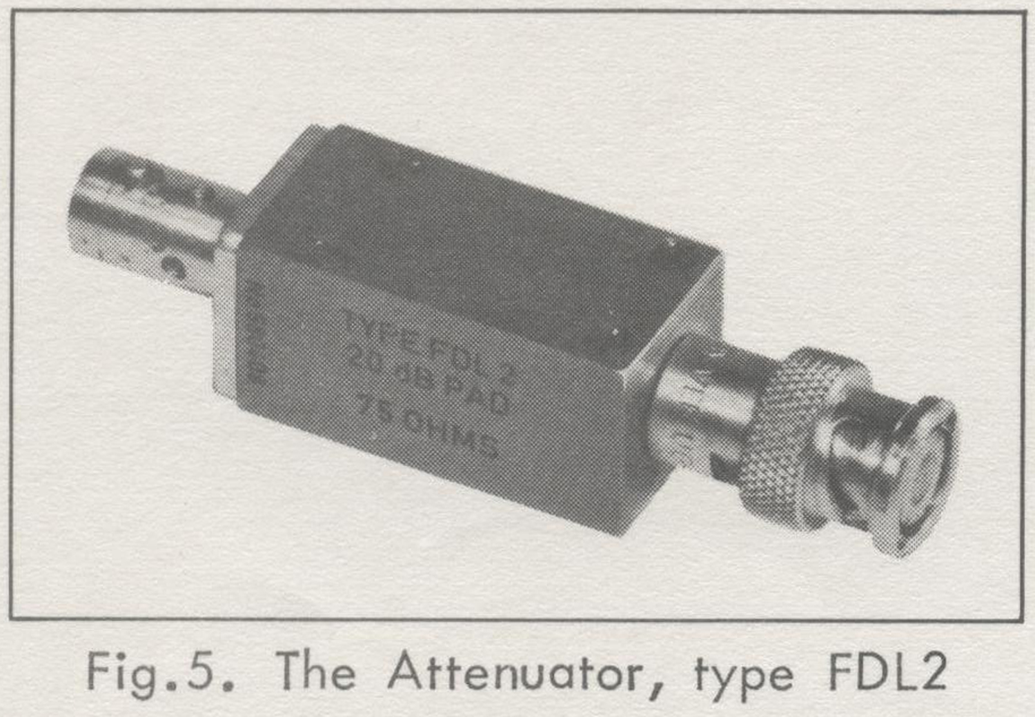
The Attenuator, type FDL2, is an attenuator to be used from dc to about 300 MHz, with 75 Ω nominal impedance.
The attenuator is constructed as a single-section pi-type resistive network. It contains high-stability carbon resistors of the film-type, selected to close tolerances.
The attenuator is completely shielded by a metal casing; no undesired electrical coupling to the internal elements is possible.
Specifications
Attenuation:     20 dB
Impedance:     75 Ω
Accuracy: Within ± 0.2 dB at dc.
Within ± 0.5 dB to 250 MHZ.
Maximum Power
Input:   0.1 watt.
Dimensions:
Height: 18 mm (¾inch)
Width: 18 mm (¾inch)
Depth: 76 mm (3 inches)
Weight: 70 grams (2 ½ oz.)
Terminals:
BNC-type coaxial connectors, male and female.
BALANCING TRANSFORMER, TYPE UBT3
General
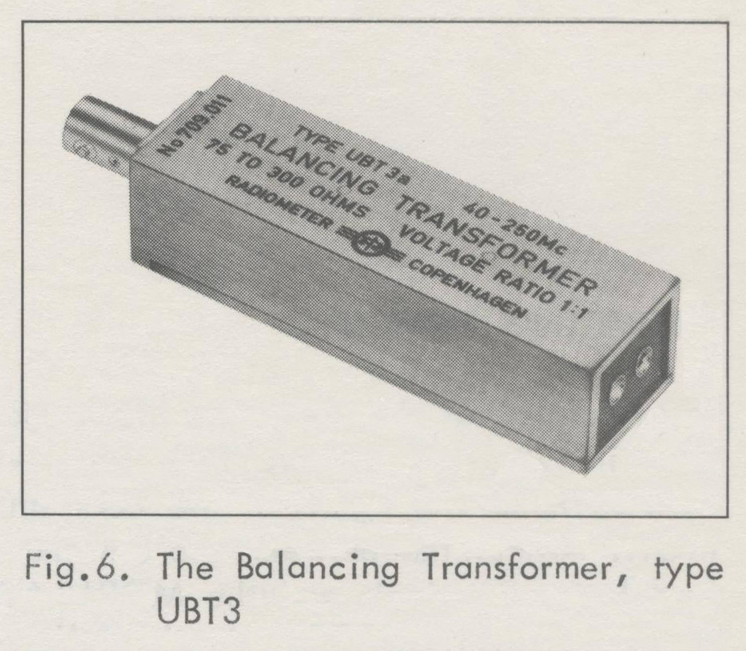
The Balancing  Transformer, type UBT3, has been designed to produce a balanced output voltage from a signal generator.
It has a voltage ratio of 1:1 ; i.e. the calibration of the signal generator can be used directly.
When the Balancing Transformer is connected to a 75 Ω  source the output impedance is 300 Ω. The balance of the output voltage is within a few per cent up to 200 MHz and within 5% to 250 MHz.
The unit contains a specially designed transformer and a resistive matching network.  It has a BNC input socket and output  from a socket which matches a commercially available 2-pin plug for twin-lead cable. One plug is supplied with the type UBT3.
Specifications
Frequency Response:
Within 1 dB from 40 MHz to 250 MHz with 300 Ω load.
Voltage Ratio: 1:1 ,
Accuracy of Output Voltage:
Within ± 1 dB of nominal value.
Output Impedance:
300 Ω when connected to a 75 Ω source.
Terminals:
Input:  BNC socket, type UG290/U.
Output:  Socket for 2-pin plug. The correct pin diameter is 3.2 mm (⅛ inch) and the spacing is 7.9 mm (5/16 inch).
Dimensions:
Height: 25 mm (1 inch)
Width: 18 mm (¾ inch)
Depth: 100 mm (4 inches)
Weight: 150 grams (5 ½ oz.)

Section D. General Description
OPERATING PRINCIPLE
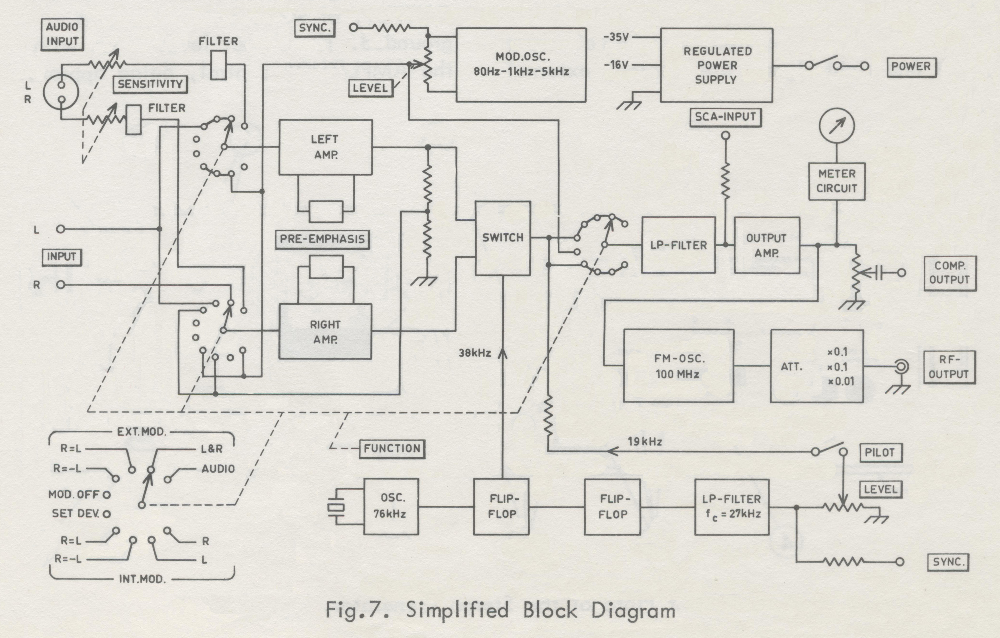
In principle, as shown on the block diagram in Fig.7, the FUNCTION SELECTOR switches the inputs of the LEFT and RIGHT AMPLIFIER between the external modulation terminals and the MODULATING OSCILLATOR  to obtain the following operating modes:
External Modulation
AUDIO:
Left and right amplifier connected to AUDIO INPUT.
Stereophonic music from tapes and records
L & R:
Left amplifier connected to L INPUT and right amplifier to R INPUT.
Normal two-channel multiplex output signal.
R = L:
Both amplifiers parallel-connected to L
INPUT.
Monophonic or Main-Channel output signal.
R = -L:
Left amplifier connected to L INPUT.
Right amplifier input signal a fraction (equal to the reciprocal amplification) of the left amplifier output voltage. Both amplifiers giving a 180 degrees’ phase shift, the output voltages of the left and right amplifier will be equal, but in opposite phase.
Stereophonic sub-channel output signal.
MOD . OFF:
Modulating circuits disconnected.
SET. DEV.:
The modulating oscillator connected directly to the output amplifier.
Internal Modulation
R = L:
Both amplifiers parallel-connected to the modulating oscillator.
Monophonic or Main-Channel output signal.
R = -L:
Left amplifier connected to the modulating oscillator.  Right amplifier input signal a fraction of the left  amplifier output voltage.
Stereophonic sub-channel output.
L
Left amplifier connected to the modulating oscillator.
Left channel multiplex signal output.
Right amplifier connected to the modulating oscillator.
Right channel multiplex signal output.
The switch modulator alternates between the left and right amplifier outputs at a frequency of 38 kHz. The switching voltage is a  38 kHz square wave signal obtained from a flip-flop.  This flip-flop is triggered by a crystal-controlled 76 kHz oscillator and feeds another flip-flop, which divides the frequency into 19 kHz (square wave). A filter smoothens this signal into a sine wave, which serves as the pilot signal and is added to the output of the switch modulator.
The switch output signal and the pilot signal pass through a phase-linear low-pass filter to the output amplifier. The amplified signal is then measured with a peak-reading meter and fed to the RF-UNIT and to the Composite Output terminals via a potentiometer. The RF-UNIT is a frequency-modulated oscillator operating  on 100 MHz and is modulated by the composite output signal from the output amplifier. Before the RF signal reaches the RF-OUTPUT terminal it may be attenuated  as much as 80 dB in steps of 20 dB. CONTROL, METER and TERMINALS.
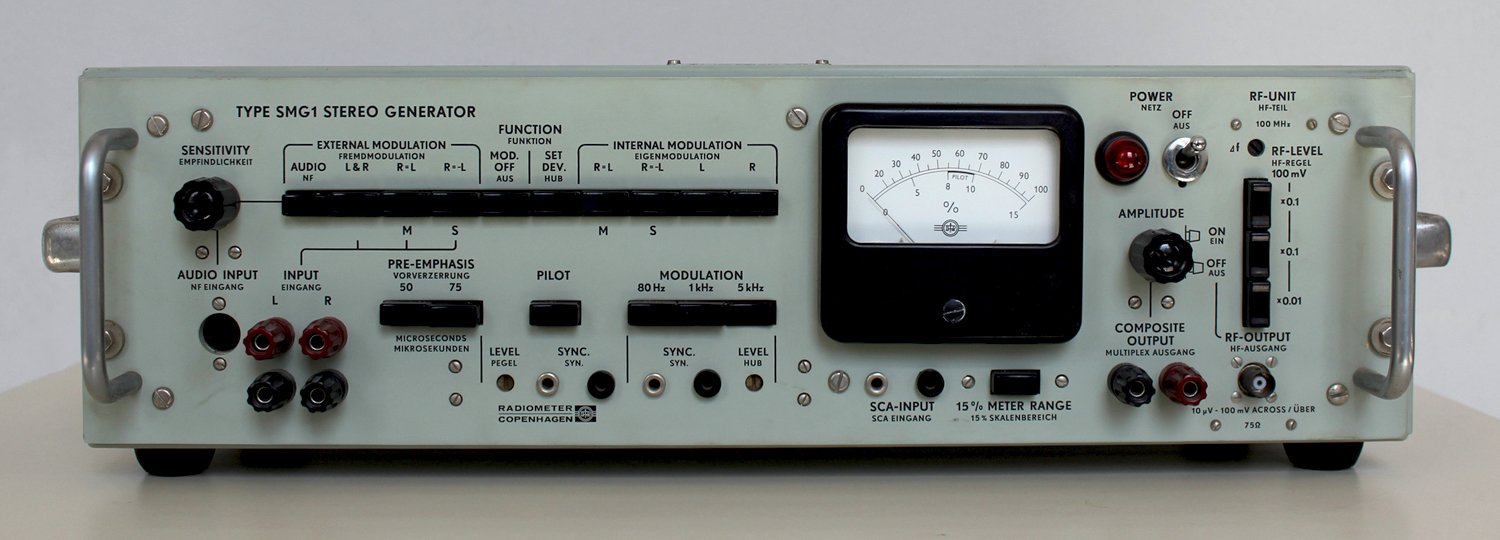
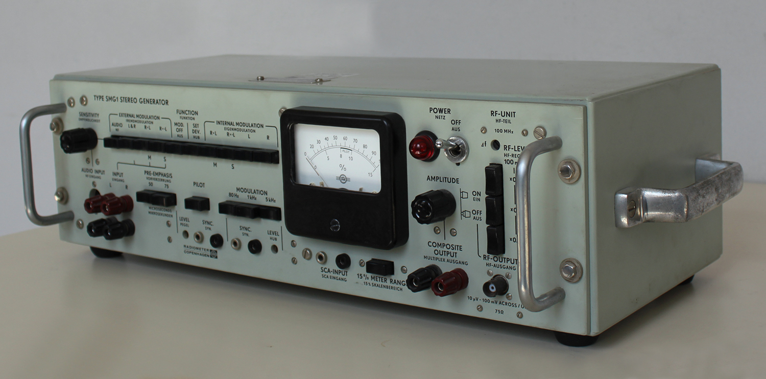
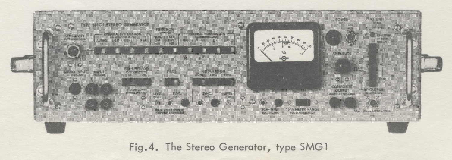
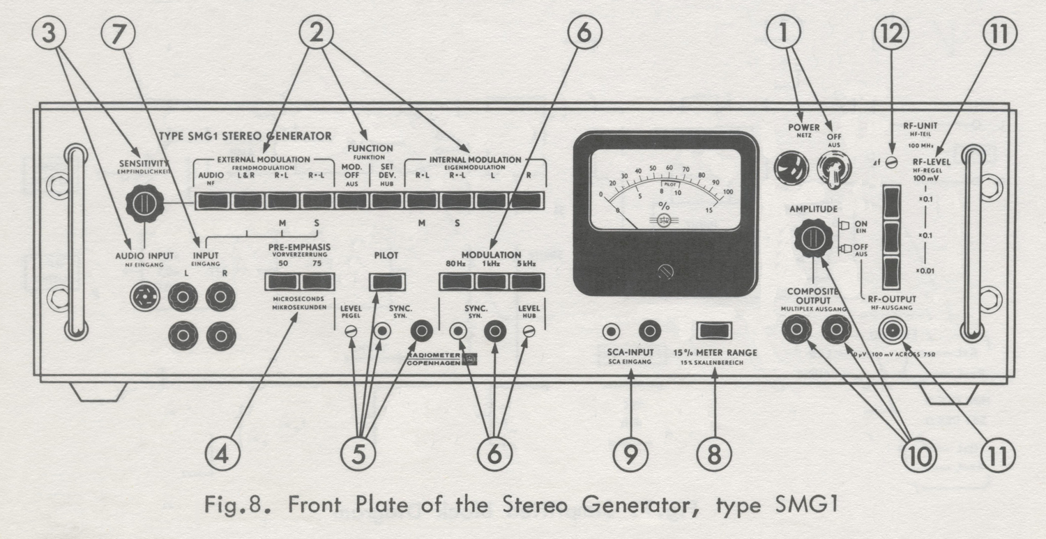
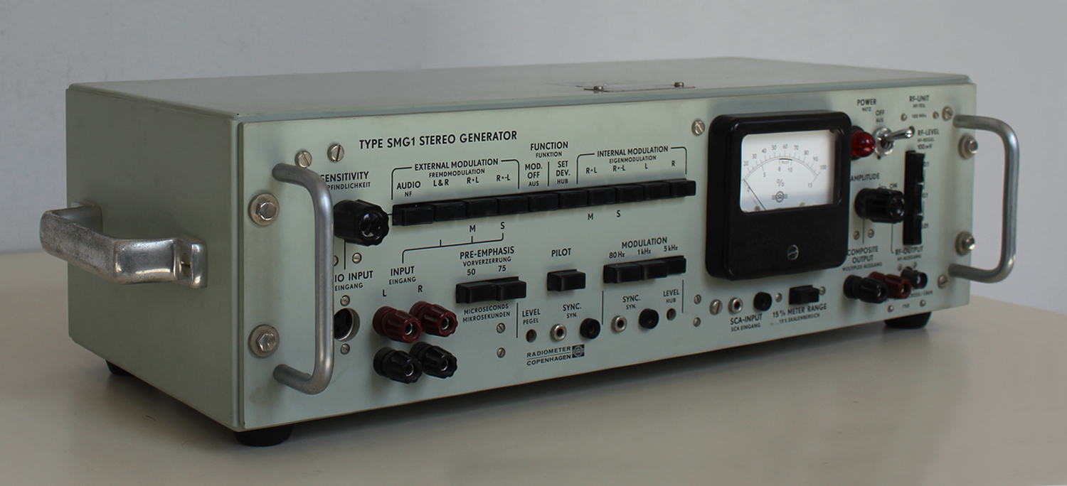
As can be seen on Fig. 8, all controls are located on the front panel.
(1)  Power Switch and Pilot Lamp
Located near the upper right-hand corner of the meter.
Pilot lamp: Neon, 220 volts.
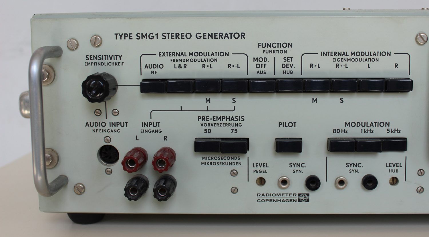
(2)  FUNCTION SELECTOR
Selects the wanted operating mode as explained above.
(3)  SENSITIVITY and AUDIO INPUT socket
The knob controls the modulation level, when an external modulation source (gramophone or tape recorder) is connected to the AUDIO INPUT five-pole socket.
(4)  PRE-EMPHASIS
With both push-buttons out, the audio frequency response is straight from 40 Hz to 15 kHz (no pre-emphasis). With one of the buttons pushed in, the pre-emphasis is 50 μsec (European standard) or 75 μsec (American standard) respectively.(5)  PILOT, pilot LEVEL and SYNC.
Pushing the pilot button switches on the 19 kHz pilot signal. The level is set with the screw-driver adjustment marked LEVEL and can be indicated on the meter (see under METER). The pilot signal is available at the SYNC. banana-plug-type terminals for synchronization purposes
(approx. 0.4 volts rms), both with the button in and out.
(6)  MODULATION FREQUENCY, LEVEL and SYNC.
Selects the desired modulation frequency when internal modulation is used. The screw-driver adjustment marked LEVEL sets the modulation level for internal modulation (see under METER).
The modulation signal is available from the SYNC. banana-plug-type terminals (approx. 2 volts rms).
(7)  L and R INPUT terminals
When other than the built-in modulation frequencies are required, or when different left and right signals are wanted, external audio signal generators have to be connected  to the left (L) and right (R) INPUT banana-plug-type terminals. The lower binding posts are grounded.
(8)  METER and METER switch
The meter indicates the peak value of the composite signal. Normally, the upper scale, graduated from 0-100% of the system  deviation, is used. By pressing the METER push-button below the meter, the range is changed to 0-15%. This range is mainly intended for setting the pilot signal level (normalized level being 8-10%). If, however, it is used to measure a complex signal  – when a weak modulation signal is applied – the accuracy is approx. 5% only.
(9)  SCA-INPUT terminals
To these banana-plug-type terminals an SCA (Subsidiary Communications Authorization) signal generator can be connected
(10)  COMPOSITE OUTPUT and AMPLITUDE control.
The composite signal is available at the two binding posts marked COMPOSITE OUTPUT, of which the left one is grounded. The output level is set with the AMPLITUDE control, being approx. 7 volts peak when the control is turned fully clockwise, and the meter reads 100%
(11)  RF-LEVEL and RF-OUTPUT terminal and RF-oscillator switch
A 100 MHz signal modulated with the signal on the COMPOSITE OUTPUT terminal  is available on the BNC connector RF-OUTPUT. By means of the RF-LEVEL push-button switch, the level of the FM- signal can be changed from 100 mV to 10 μV in steps of 20 dB.
The peak-deviation is 75 kHz when the meter reads 100%.
The RF-oscillator can be switched off by pulling the knob of the AMPLITUDE control.
(12)  Δf
To avoid interference from a local broadcasting station operating on a frequency close to 100 MHz, the carrier frequency of the FM-signal can be changed approximately ± 0.5 MHz with this screw-drive adjustment.
Line Voltage Receptacle, Fuse, and Voltage Selector
Are all located on the rear of the cabinet.Section E. Operating Instructions
CONNECTION
Power
Before connecting the instrument to the power line, make sure that the line voltage  selector is set to the voltage of the power line. The voltage selector is always set to 220 volts when the instrument leaves the factory.
To change to another voltage, loosen the centre screw on the voltage selector, and set the selector to the desired voltage.
The selector is accessible from the back of the cabinet. If the voltage is changed, it may also be necessary to exchange the fuse located in the selector.
The fuse type should be 80 mA, slow-blow, for 200, 220 and 240 volts, and 160 mA, slow-blow, for 110, 115 and 127 volts.
The generator is ready for use a few seconds after being connected to the power line. The first time some of the push-buttons are operated after connecting up, the meter-pointer will jump to full deflection, because the electrolytic capacitors are being charged. However, this will not damage the instrument.
External Modulating  Sources
Gramophone or Tape Recorder.
The gramophone or tape recorder should be provided with amplifiers able to give at least 350 millivolts peak. The amplifiers  should give the de-emphasis required for the employed playback system.
A plug, type Preh 8-7506, or the like should be used to connect the gramophone or tape recorder to the AUDIO INPUT.
The order of the connections, which complies with the DIN 41524 recommendations, appears from the circuit diagram appended to this manual.
The B & O types 610 VF, 41 VF and 42 VF stereo gramophones with built-in amplifiers  can be used direct (Manufacturer: Bang and Olufsen, Struer, Denmark).
External Audio Signal Generators.
External modulation sources used for  measurements should always be connected to the L and R terminals (binding posts).
Normally, unshielded leads will suffice, but in case of hum, shielded cables should be used.
When an M (R = L) output signal or an S (R = -L) output signal is wanted, the audio signal generator must be connected to the L-terminal. In other cases, the generator is connected to the L- or R- terminal, as required.
If different left and right signals are wanted, use either two external generators connected to the L and R terminals, or connect the L terminal to an external audio generator, and the R terminal (or vice versa) to the MODULATION FREQUENCY SYNC. terminal with a variable resistor shunting the terminals to ground.
Then choose the R signal modulation frequency with the MODULATION FREQUENCY switch, and set the level with the variable resistor.
SCA Sub-Carrier.
To add a normalized SCA sub-channel signal to the composite stereo signal, a frequency-modulated oscillator should be connected to the SCA INPUT terminals.
The carrier frequency should be approx. 67 kHz, the peak-deviation 7 kHz, and the output voltage approx. 250 millivolts.
COMPOSITE OUTPUT to a stereo adapter
Connect  COMPOSITE OUTPUT to the adapter. To avoid distortion, make sure that the load impedance is at least 1500 Ω. lf a shielded cable is used, check also that the capacitive load does not exceed 300 pF.
RF-OUTPUT to Antenna Input of a receiver
For approx. 75 Ω input impedance of the receiver antenna terminals, connect a 75 Ω coaxial cable from the RF-OUTPUT terminal direct to the receiver antenna terminals. It the input impedance is 300 Ω, use a 75/300 Ω Balancing Transformer, type UBT3, in front of the receiver.
If other output voltages or a better standing  wave ratio than those specified for the Stereo Generator are required, insert an appropriate 75 Ω pad between the Stereo Generator and the cable.
Modulating an external FM Signal Generator
When making measurements on other  frequencies than 100 MHz or with continuously  variable output voltages, an external  FM signal generator should be used.
This signal generator should be able to handle modulation frequencies up to 75 kHz with negligible amplitude – and phase – distortion.
Proceed as follows:
1) Connect COMPOSITE OUTPUT terminals to the External Modulation terminals of the signal generator. If necessary, use a shielded cable. Make sure that the load does not exceed the limiting values (see above).
2) Set the signal generator to External FM and to the required carrier frequency.
3) Push MODULATION FREQUENCY button  1 kHz and FUNCTION SELECTOR button SET. DEV. of the Stereo Generator. With the modulation LEVEL adjustment in correct setting, the meter will now read 100%.
4) Turn AMPLITUDE knob of the Stereo Generator and/or the modulation level knob of the signal generator, until the modulation meter of the signal generator reads 75 kHz peak-deviation.
5) When now modulating with the complex stereo signal, the peak-deviation will be 75 kHz, when the meter of the Stereo Generator reads 100%, and of proportional  values for lower readings. For a complex  stereo signal, the modulation meter of the signal generator will not always read the peak deviation of the stereo FM-signal, as the Stereo Generator meter does.
OPERATING MODES
Modulation from gramophone or tape recorder for listening tests
1) Connect the gramophone or tape recorder as described above.
2) Push buttons AUDIO, PRE-EMPHASIS (50 μsec European standard, or 75 μsec American standard) and PILOT.
3) Turn SENSITIVITY knob, so that the meter reads 50-70% during loud passages in the music.
Internal Modulation
1) Push buttons PILOT and PRE-EMPHASIS (50 μsec or 75 μsec, European and American standard, respectively), if pilot signal or pre-emphasis is desired for the measurements in progress.
2) Push the desired MODULATION FREQUENCY button: 80 Hz, 1 kHz or 5 kHz. 80 Hz, 1 kHz or 10 kHz for SMG1S2.
3) For the following operating modes, push the appropriate FUNCTION SELECTOR  buttons located below the inscription INTERNAL MODULATION:
Monophonic channel output:
R = L  (M)
Stereophonic sub-channel output:
R = – L (S)
Left channel multiplex signal output:
L
Right channel multiplex signal output:
R
Note:
If a modulation level different from the preset level is desired, turn the screw-driver adjustment marked LEVEL, use external  modulation below, or use the arrangement described above.
When pre-emphasis is inserted, the  modulation level obtained for a 5 kHz (10kHz for SMG1S2) modulation frequency is almost normal, whereas the modulation levels obtained for modulation frequencies of 1 kHz and 80 Hz are lower.
External Modulation
1) Push buttons PILOT and PRE-EMPHASIS (50 μsec or 75 μsec, European and American standard, respectively), if pilot signal or pre-emphasis is wanted for the measurements in progress.
2) For the following operating modes, connect  the external audio signal generator(s) (see also above), and push the appropriate FUNCTION SELECTOR buttons, located under the inscription EXTERNAL MODULATION, as described below:
a) Monophonic channel output:
Connect the external generator to L INPUT terminals. Push button R = L (M)
b) Stereophonic sub-channel output:
Connect the external generator to L INPUT terminals. Push button R = – L (S).
c) Left channel multiplex signal output:
Connect the external generator to L INPUT terminals. Push button L & R.
d) Right channel multiplex signal output:
Connect the external generator to R INPUT terminals. Push button L & R.
e) Simultaneous left and right channel multiplex output:
Connect the external generators to L and R INPUT terminals. Push button L & R.
3) Set the external generators(s) to the desired frequency (frequencies) and to the appropriate output level(s) – read the meter of the Stereo Generator.
Note:
If different left and right signals are wanted, but only one audio signal generator is  available, use the built-in modulating oscillator as the second one.
Special Operating Modes
1) Non-standard pilot amplitude or phase.
The standard pilot amplitude gives a  frequency deviation that is 8-10% of the maximum deviation (75 kHz). To obtain a non-standard value, push buttons  PILOT, MOD. OFF and METER, and turn the screw-driver adjustment marked LEVEL, until the meter reads the desired pilot signal amplitude. Although not specified, a pilot amplitude giving more than 20% deviation can be obtained. To measure amplitudes that correspond to deviations larger than 15%, release the METER button and read the upper scale.At the plant, the pilot signal phase has been internally adjusted to the standard value. If a non-standard pilot phase is required, connect the variable low-pass filter as shown in Fig.9 between the  PILOT SYNC. and SCA INPUT terminals, and release the PILOT button. The pilot amplitude will have the standardized  value simply by turning the variable double -capacitor of the filter. See MAINTENANCE  as regards finding the setting of the capacitor which gives the correct pilot phase.
If, moreover, a smaller non-standard pilot amplitude is wanted, shunt the PILOT SYNC. terminal (to which the input of the filter still is connected) with a variable  resistor to ground, and then set the amplitude with this resistor.
2) Using the Stereo Generator as a low-distortion audio signal generator.
Push FUNCTION SELECTOR button SET DEV. and one of the MODULATION FREQUENCY buttons. 80 Hz, 1 kHz or 5 kHz, . (80 Hz, 1 kHz or 10 kHz for SMG1S2.) The signal at the COMPOSITE OUTPUT terminals will now be a pure sine-wave of the chosen frequency. Voltage: 0-5 volts rms, depending on the setting of AMPLITUDE and LEVEL.
Distortion: Less than 0.2%. Load impedance: minimum 1500 Ω.
3) FM-Modulating the RF-UNIT with an external modulation signal.
a) Modulation frequencies approx. 40 Hz – 15 kHz.
Push FUNCTION SELECTOR button marked EXTERNAL MODULATION
R = L (M)
Connect the external audio signal generator to L INPUT terminals.
Set the output voltage of the audio signal generator to full deflection (100%) on the meter, if 75 kHz peak deviation is wanted, and proportionally lower for smaller peak deviations.
b) Modulation frequencies approx. 10 kHz – 75 kHz.
Push FUNCTION SELECTOR button marked MOD. OFF.
Connect the external signal generator terminals.
Set the output voltage of the signal  generator to full deflection (100%) on the meter, if 75 kHz peak deviation is wanted, and proportionally lower for smaller peak deviations.
Section F. Circuit Description
INPUT CIRCUITS, FUNCTION SELECTOR and INPUT AMPLIFIERS
The input circuits are connected to the input amplifiers so as to provide the required operating modes.
Input Amplifiers
The left and right input amplifiers are two identical amplifiers equipped with three transistors each. Heavy negative feedback is used to obtain constant amplification and small phase error. 50 μsec (European standard) or 75 μsec (American standard) pre-emphasis can be switched into the feedback loop.
The outputs from these amplifiers feed the switch modulator.
Audio Input
The Audio Input provides for stereo inputs from tapes and records. A two-gang  potentiometer provides for sensitivity control, and two low-pass filters with a cut-off frequency of 15 kHz suppress spurious signals, particularly at 19 kHz.
In position AUDIO), the Function Selector connects the Audio Input to the input amplifiers.
L and R Input
This input circuit is intended for measurements  where external audio signal generators are used.
With Function Selector in position L & R, the L Input and R Input terminals are coupled to the left and right input amplifier respectively.
In position R = L, the L Input terminals are coupled to the parallel-connected left and right input amplifiers.
In position R = -L, the L Input terminals are connected to the left input amplifier. The input signal to the right input amplifier  is nearly half the sum of the output signals from the two input amplifiers. The summation is a bit skewed to obtain  exactly balanced driving signals to the switch modulator.
Operating Modes MOD. OFF and SET DEV.
With Function Selector in position MOD. OFF, the connection between the switch modulator and the low-pass filter in front of the output amplifier is open. Therefore there is either no input signal to the output
amplifier, or, if the PILOT button is pushed, the input signal is the pilot signal only.
In position SET. DEV., the Modulating Oscillator supplies a pure sine-wave signal to the output amplifier.
Internal Modulation
With Function Selector in position R = L, the left and right input amplifiers are parallel-fed from the built-in modulating oscillator.
In position R = -L, the left input amplifier  is fed from the modulating oscillator, and the input signal to the right input amplifier is nearly half the sum of the output signals from the two input amplifiers.
In this way balanced driving signals to  the switch modulator are obtained.
In position L ONLY, the left input amplifier  is fed from the modulating oscillator, and the right input amplifier is short-circuited to ground. Vice versa in position R ONLY.
MODULATING OSCILLATOR
The modulating oscillator is a 3-transistors1 Wien-bridge RC-oscillator with a thermistor for amplitude stabilization.
Three modulation frequencies can be chosen by switching the capacitors in the Wien-bridge circuit.
The modulation level is set by means of a screw-driver adjustment. The oscillator signal is accessible from the Sync. terminals».
§§§
Il testo prosegue nella seconda parte; per consultarla scrivere “SMG1” su Cerca.
 Foto di Claudio Profumieri; elaborazioni, ricerche e testo a cura di Fabio Panfili.


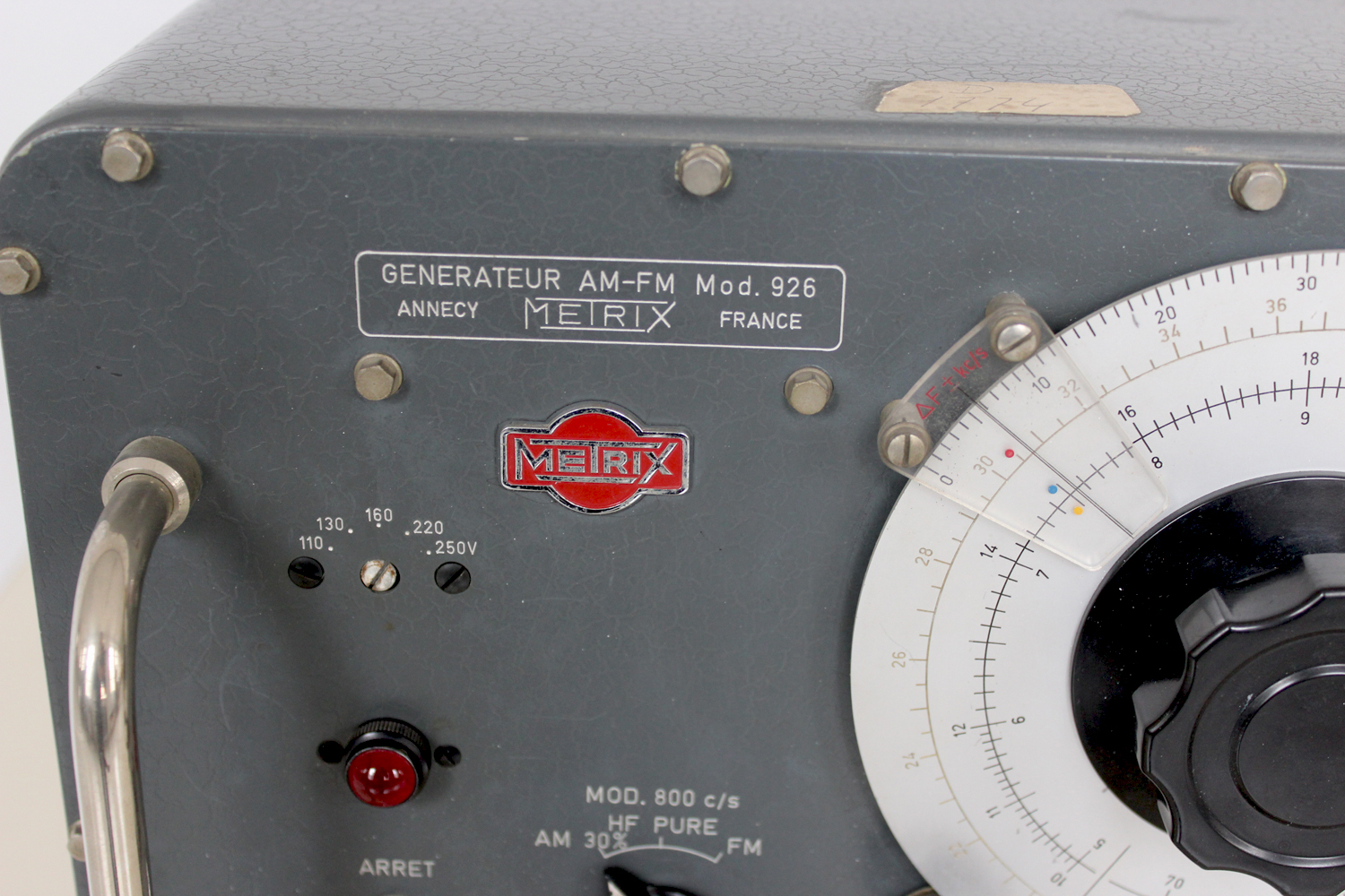
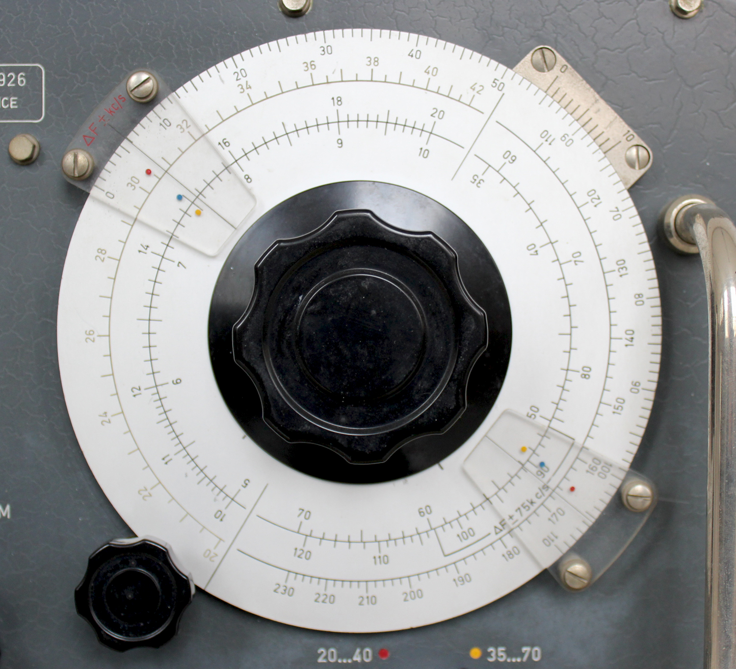
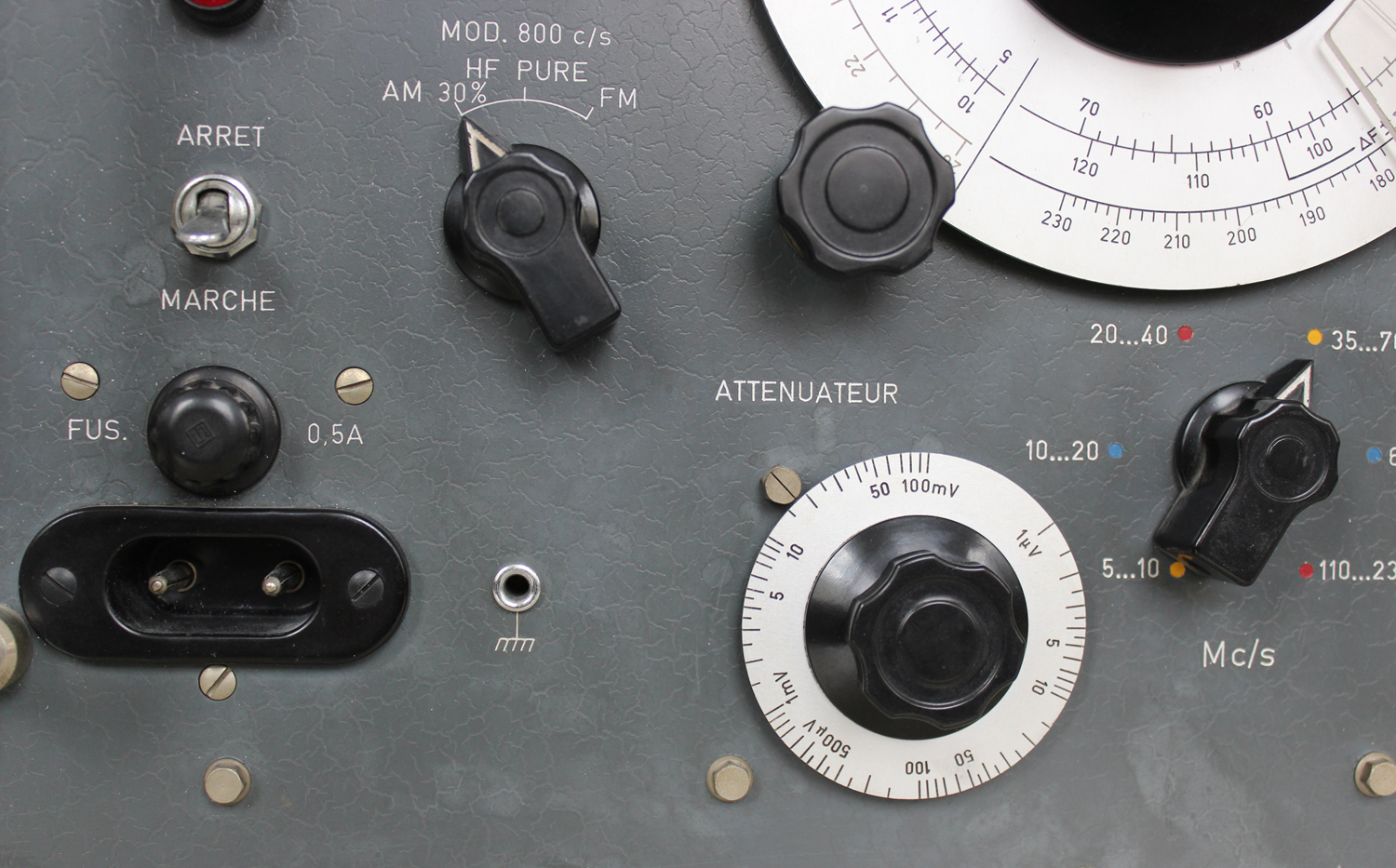
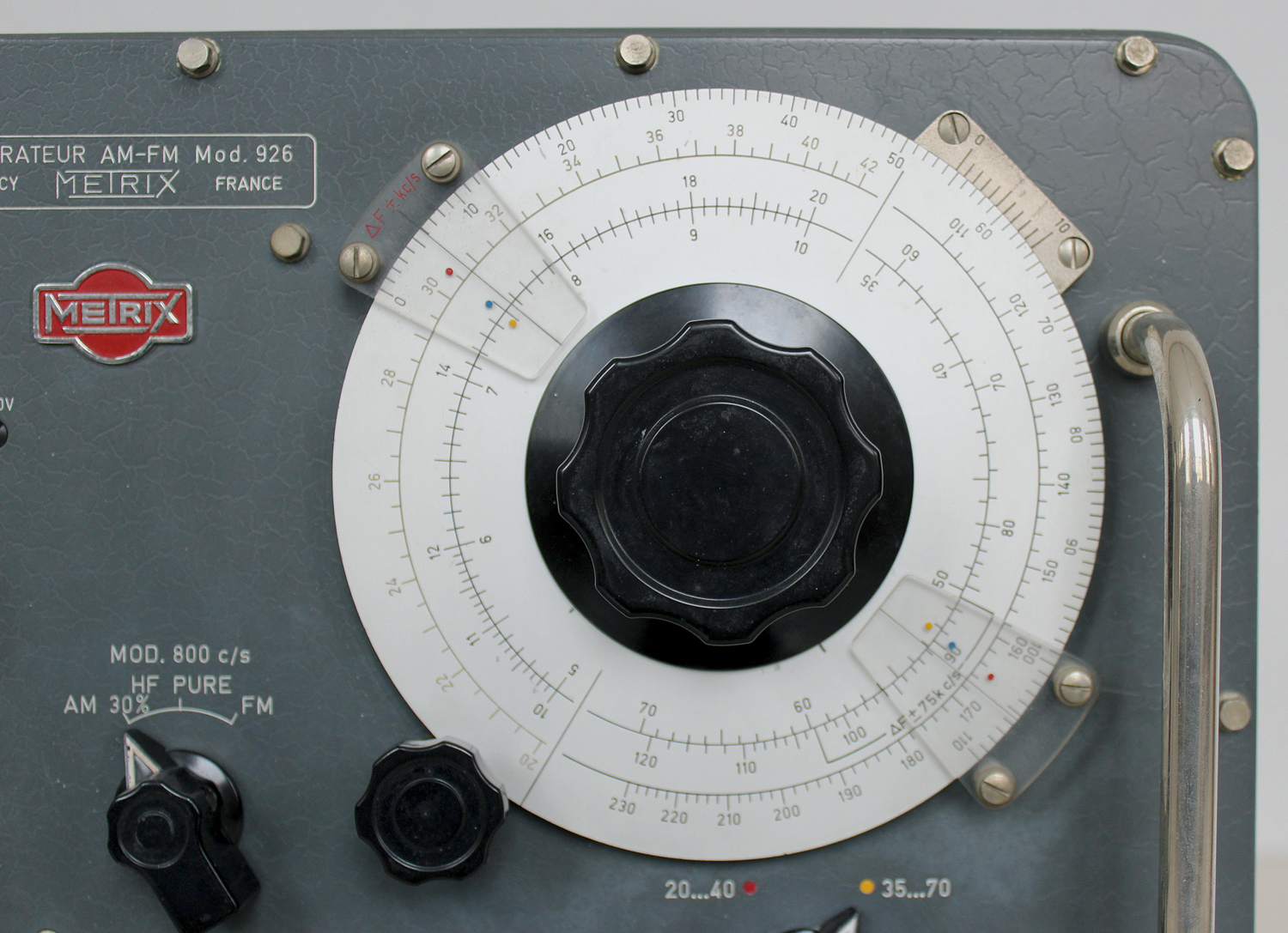
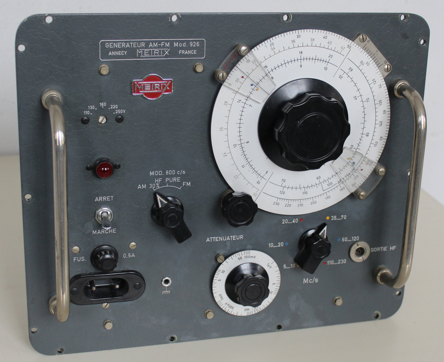
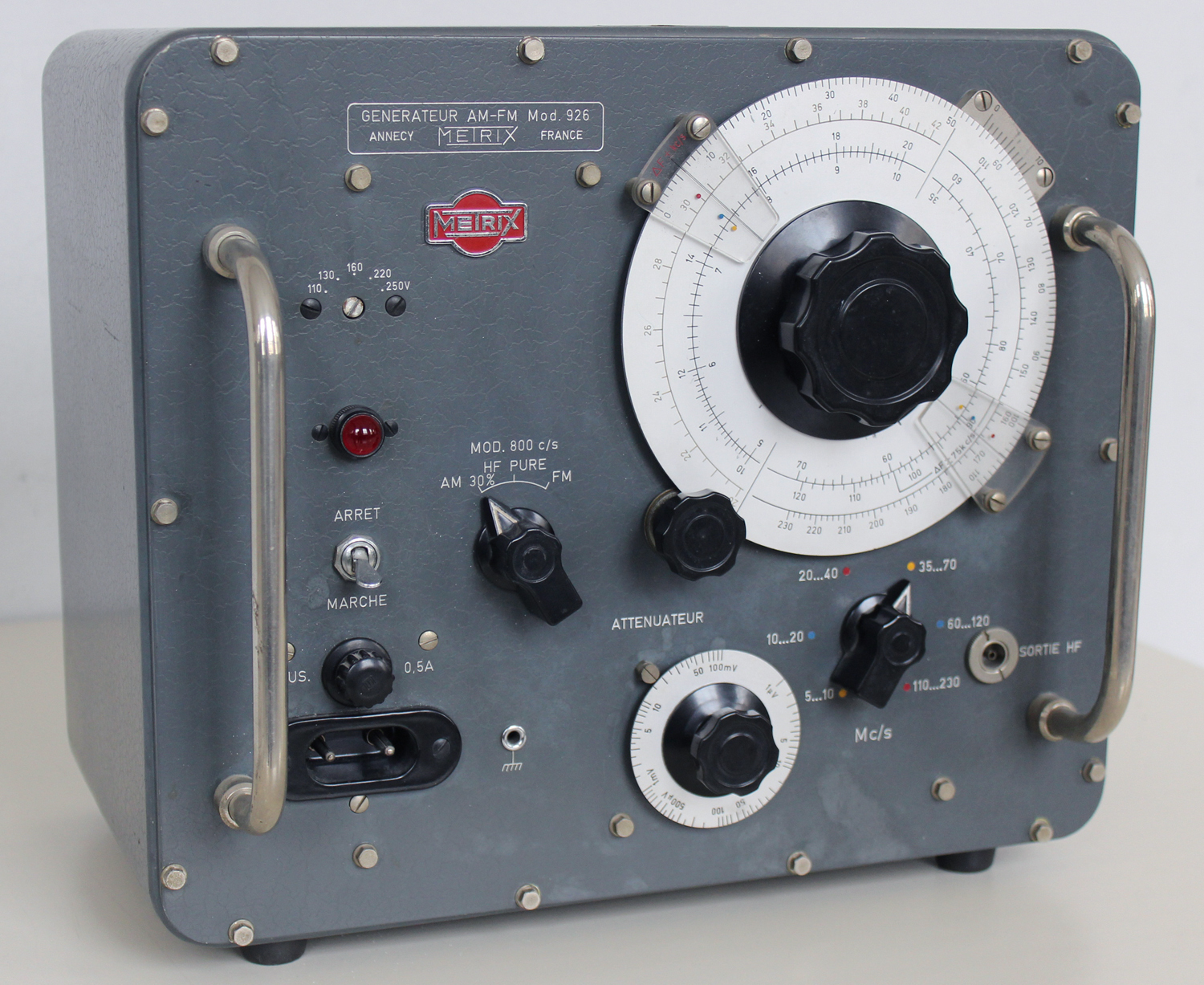
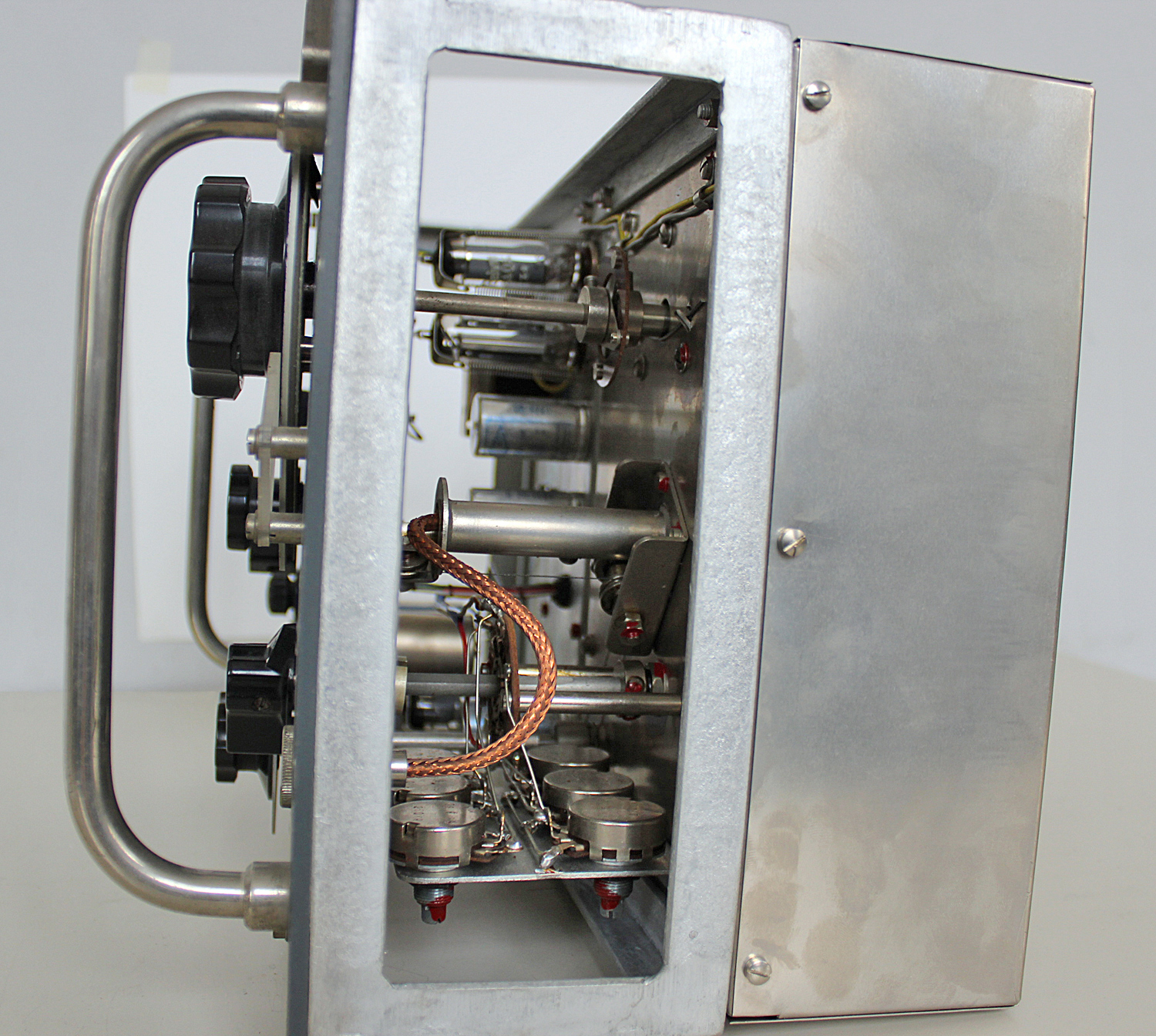
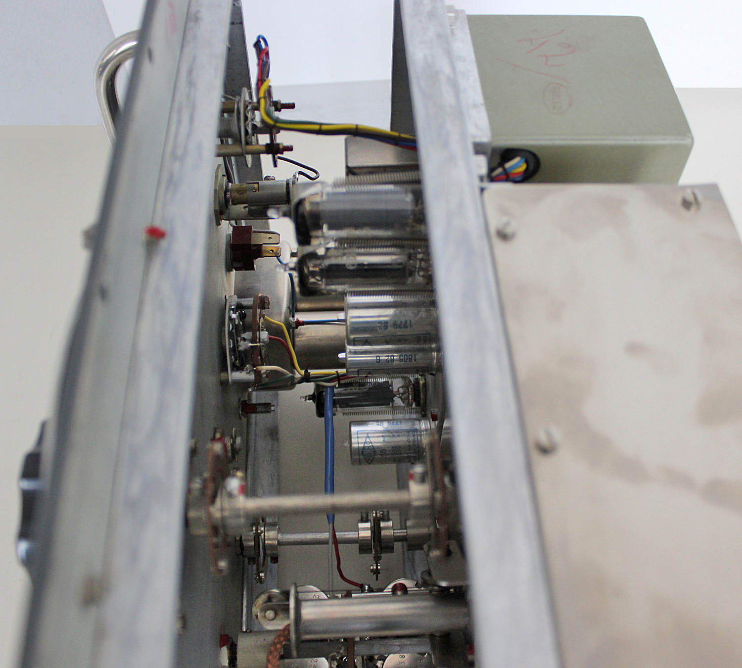
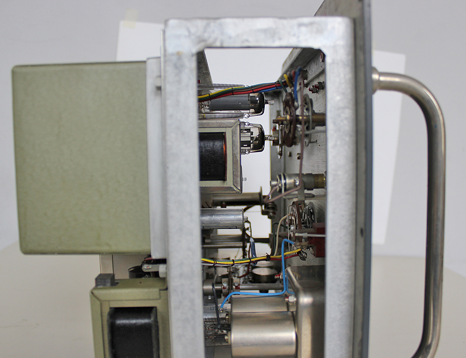
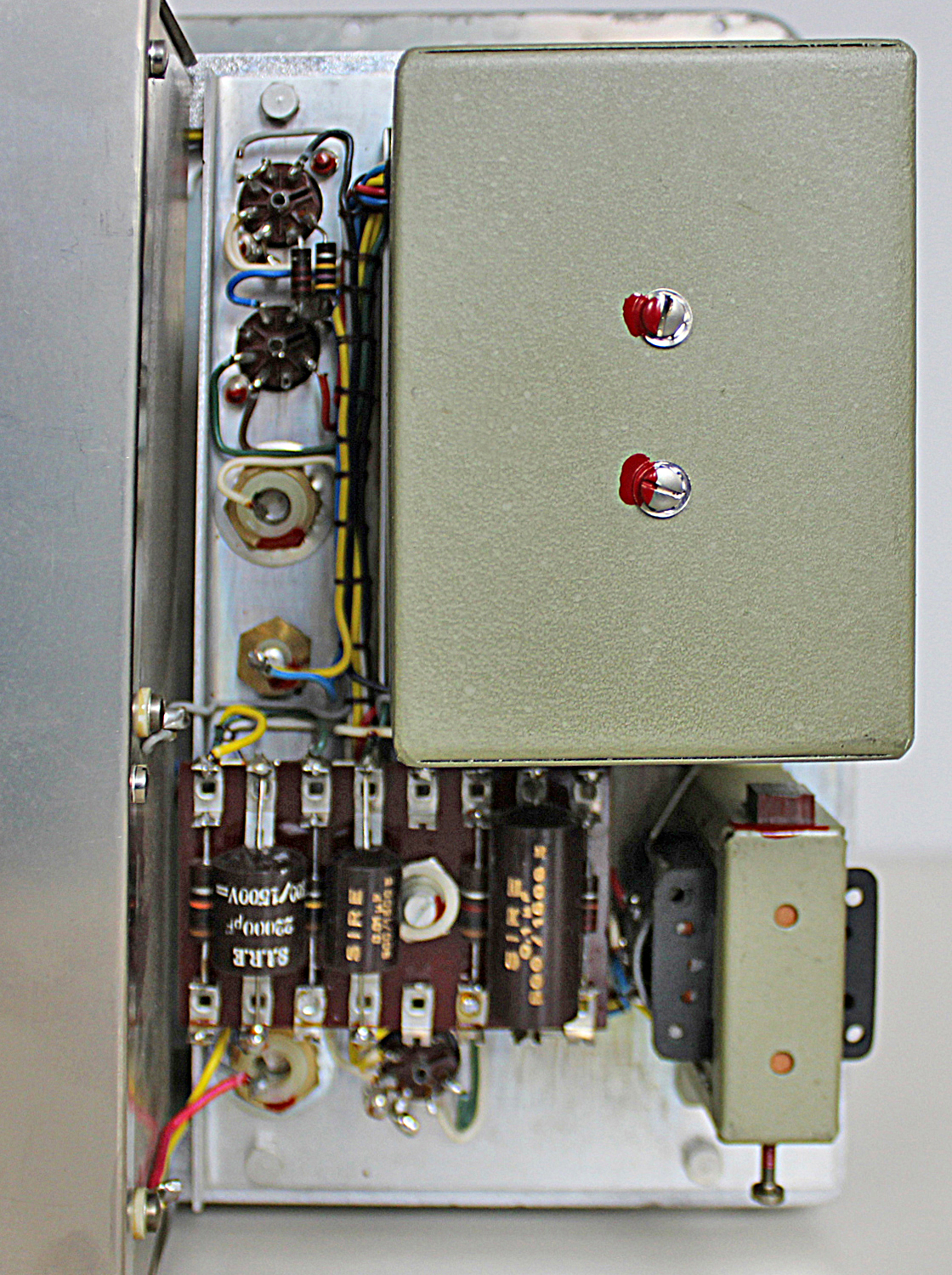
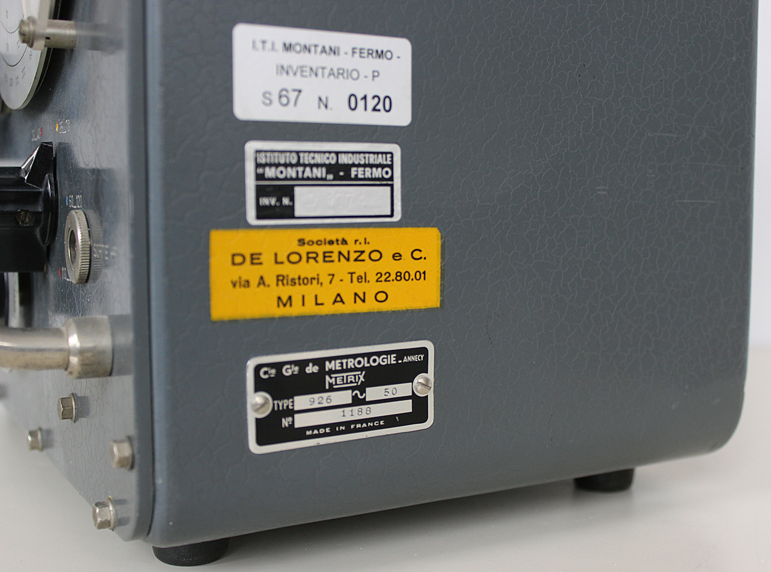
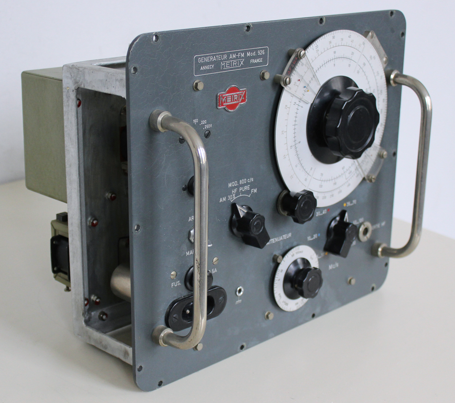
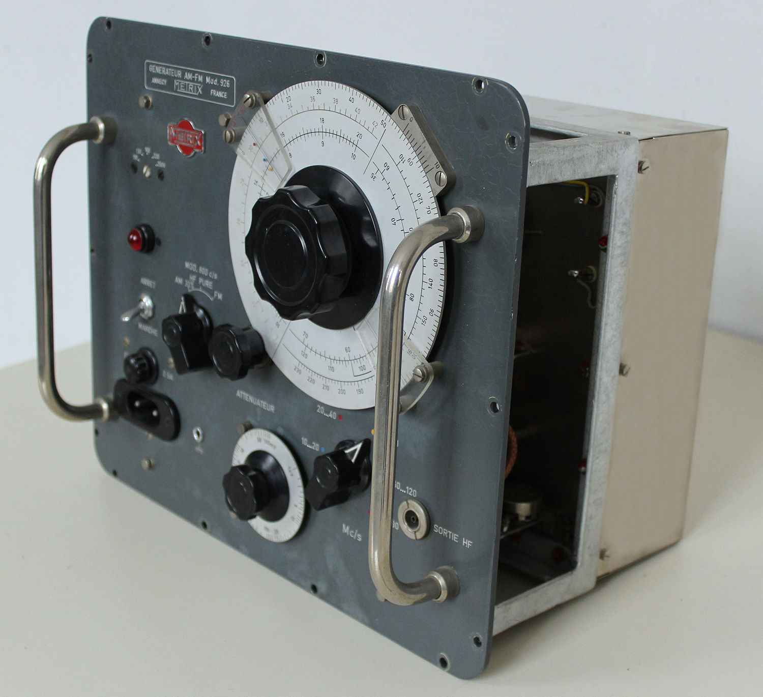
Generateur AM- FM METRIX, Modèle 926, Numéro de série 1188

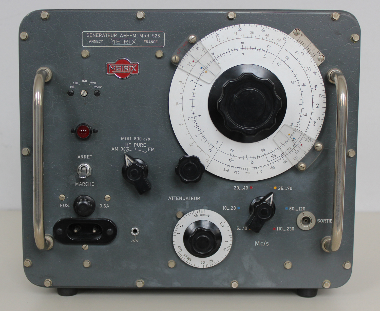
GENERATEUR AM- FM METRIX Modèle 926, Numéro de série 1188.
Nell’inventario D del 1956, in data 31 marzo 1960, al n° 1774 si legge: “ing. Ugo de Lorenzo – Milano. Generatore AM – FM Metrix – mod. 926. Destinazione Radiotecnica”.
Rappresentanza generale per l’Italia ing. UGO DE LORENZO & C. S.R.L. – MILANO.
Riportiamo qui di seguito il testo di istruzioni conservato presso la Sezione Elettronica.
§§§
«COMPAGNIE GENERALE DE METROLOGIE  METRIX ANNECY  FRANCE

GENERATEUR AM – FM  Modèle 926

MODE D’EMPLOI

TABLES  DES MATERIES

I – GENERALITES

II – FONCTIONNEMENT

III – CARACTERISTIQUES TECHNIQUES

IV – MODE D’EMPLOI

V – ENTRETIEN

Annexe: Liste des pieces électriques. Schéma de principe. Emplacement des pièces.

I – GENERATEUR AM – FM – Modèle “926”. GENERALITES –
Le Générateur 926 fournit une tension HF couvrant une gamme de Fréquences comprises entre 5 et 230 Mc/s. Il satisfait donc largement aux besoins de la télévision et de la modulation de fréquences. Il peut être utilisé dans les chaînes de fabrication ainsi que dans les stations-service.
La tension des signaux délivrés est réglable continuellement de 1 μV à 100 mV par un atténuateur à piston et est lue directement sur le cadran de cet atténuateur.
L’onde HF peut être modulée par un oscillateur interne à la fréquence de 800 c/s soit en amplitude, soit en fréquence.
Pour la modulation en amplitude, le taux est fixe et ajusté à 30 %. Il est à noter que la tension de sortie maximum de 100 mV permet d’utiliser des appareils de modulation extérieure, (par exemple modulateur  à cristal METRIX modèle 56) et de disposer à la sortie de ces derniers d’une tension suffisante pour la plupart des mesures classiques, sans modulation de fréquence parasite.
Le taux de modulation en fréquence est connu pour chaque fréquence HF et sa valeur est indiquée par le cadran de fréquence. Il est compris entre 40 et 80 kc/s d’excursion totale sur toutes les gammes HF, sauf sur la gamme 60…120 Mc/s. Sur celle-ci l’excursion totale entre 86 et 103 Mc/s (bande FM) est de 150 kc/s.

 II- FONCTIONNEMENT – (voir schéma de principe) –
A) BLOC OSCILLATION.
L’Oscillateur du type COLPITTS modifié -(ULTRA-AUDION)- comporte un circuit d’accord branché entre grille et anode du tube oscillateur V3. Le taux de réaction est fixé par les capacités internes du tube. L’arrivée  haute tension s’effectue à une extrémité des bobines à travers la résistance R5.

Le condensateur variable d’accord est du type équilibré à rotor non connecté, ce qui exclut tout contact mobile susceptible à la longue de perturber le fonctionnement de l’oscillateur.

B) SORTIE
Un atténuateur à piston, guide d’onde travaillant au-delà de la fréquence de coupure, constitue le dispositif de sortie. Chaque bobine de 1’oscillateur est amenée devant le guide d’onde et le piston portant la bobine de couplage se déplace dans le champ magnétique développé dans le tube.

III – CARACTERISTIQUES TECHNIQUES.
Fréquences couvertes: 5 à 230 Mc/s en 6 gammes;
5… 10 Mc/s, 10… 20 Mc/s, 20… 40 Mc/s, 35.. 70 nMc/s, 60…12 mC/s et 110… 230 Mc/s.

Précision de fréquence:  ± 1 % L’étalonnage en fréquence est effectué pour une tension de sortie lue sur l’atténuateur de 100 mV.

Stabilité globale en frequence: 0,5 % compte tenu de variations de ± 10 % de la tension secteur.

Tension de sortie HF: progressivement réglable de 1 μV à 100 mV. Un atténuateur livré avec le générateur permet de fermer la sortie sur 75 Ω en divisant la  tension dans le rapport 1 : 10. Le câble d.’impédance caractéristique 75 Ω livré avec le générateur est ouvert.

Précision de la tension maximum de sortie: ± 30 % (sortie du générateur fermé sur 75 Ω)

Précision de l’atténuation:  ± 1 dB jusqu’à 10 μV.

Rayonnement: non décelable par les récepteurs usuels.

Modulation en amplitude: 800 c/s  ± 5 sinusoïdale taux de modulation:  30 % précision du taux de modulation: ± 10 % jusqu’à 120 Mc/s; au- dessus ± 20 %.

Modulation en fréquence: 800 c/s ± 5 %  sinusoïdale excursion totale 40 à 80 kc/s sur les gammes 5… 10, 10… 20, 20… 40, 35… 70 et 110… 230 Mc/s, précision de 1’excursion  ± 10 % jusqu’à 70 Mc/s ; au-dessus de 110 Mc/s: ± 30 % gamme 60… 120 Mc/s: excursion totale entre 86 et 103 Mc/s = 150 kc/s ± 10 %.

Alimentation: 110 -130 – 160 – 220 – 250 V, 50… 60 c/s

Consommation: 24 VA environ.

Tubes utilisés: 1× EC92, 2 × 6AQ5, 1 × 6X4.

Poids: 11 kg.

Dimensions (hors tout): 530 × 295 × 240 mm.

Composition de la fourniture:

1 Générateur 926

1 Bon de garantie

1 Mode d’emploi

1 Cordon secteur AG 10

1 Câble HF 759 Ω  HB 73

1 Atténuateur 20 dB 75 Ω AA 109

3 Fusibles de rechange 0,5 A AA 97

IV – MODE D’EMPLOI –
Avant de brancher le générateur au secteur, s’assurer que le contacteur secteur est dans la position correspondant à la tension du secteur et que la fréquence de celui-ci est de 50 ou 60 c/s.

A) CHOIX DE LA GAMME.
Le bouton-flèche situé sous le cadran principal entraîne la rotation du tambour sur lequel sont disposés les bobinages oscillateurs.
Le tambour pouvant rester entre deux positions, veiller lors d’un
changement de gamme à bien positionner celui-ci. L’enclanchement se fait d’ailleurs avec précision et sans ambiguité par un encliquetage des lames-ressorts dans les encoches situées à la périphérie du tambour. L’accouplement mécanique entre le bouton de comande et le rotacteur présente un jeu qui évite de freiner 1’encliquetage. La position du tambour porte-bobines est donc indépendante de 1’action de l’opérateur et le retour à une même fréquence après comutation est assuré.

B) LECTURE DE LA FREQUENCE.
Elle s’effectue directement sur le cadran principal. Si le bouton-flèche est orienté uers la gauche (gammes 5… 10, 10… 20, 20… 40 Mc/s) on lit sur l’index situé en haut et à gauche du cadran. Si le bouton-flèche est orienté vers la droite (gammes 35… 70, 60…120, 110… 230 Mc/s) 1a lecture s’effectue sur l’index situé en bas et à droite du cadran principal.
La fréquence est affichée sur chaque index sous le point de même couleur que le point indiqué par le bouton de gammes.
Pour ajuster une même fréquence à plusieurs reprises avec precision on peut se servir de 1’échelle extérieure graduée de 0… 110 et lire sur le vernier qui peut être utilisé également pour interpoler entre 2 graduations.

C) AJUSTAGE DE LA TENSION DE SORTIE.
Pour régler la tension de sortie, ajuster le cadran de 1’atténuateur à la valeur désirée. La précision et le réglage sont indépendants du taux de modulation en amplitude ou en fréquence. La tension indiquée par 1’atténuateur est disponible quand la sortie du générateur est fermée sur une résistance de 75 Ω.

D) CHOIX DE LA MODULATION.
Le contacteur de modulation comporte trois positions: AM 30 % à gauche, HF PURE au centre et FM à droite.
Dans la position AM 30 % 1a tension de sortie est modulée en amplitude au taux constant de 30 % par une fréquence de 800 c/s.
Dans la position FM la tension de sortie est modulée en frequence également par 800 c/s. L’excursion en fréquence est indiquée en kc/s par l’échel1e graduée en rouge sur le cadran principal (cette échelle est également la gamme 20… 40 Mc/s). La lecture en kc/s sur l’échel1e rouge est la demi-excursion totale ΔF/2  pour toutes les gammes sauf pour la gamme 60… 120 Mc/s. Sur cette gamme ΔF/2  est de 75 kc/s ± 10 % entre 86 et 103 Mc/s. Pour le reste de cette gamme on peut déterminer le ΔF en utilisant 1’échel1e rouge comme pour les autres gammes et en multipliant la lecture du ΔF par 2,3.

ENTRETIEN – (Voir Emplacement des pièces).
Le générateur étant étanche aux poussières, l’appareil exigera un entretien à peu près nul. On nettoiera si nécessaire les contacteurs au trichlorèthylène sans les graisser après nettoyage. Seuls les deux lampes de contact du rotacteur HF seront très légèrement graissées après nettoyage avec une huile de paraffine très pure (qualité médicale). L’encliquetage du tambour peut être graissé, après nettoyage, avec de la vaseline. On évitera de toucher les bobines du tambour, ce qui risquerait de fausser l’étalonnage en fréquence.
Un remplacement des pièces suivantes exige un nouvel étalonnage du générateur: transformateur BF (T2), modulateur FM (L9), tous les potentiomètres (P1 à P7), les bobines HF (L2 à L7) et le condensateur variable (C7).
Les autres pièces détachées peuvent être remplacées sans perturber le fonctionnement du générateur en utilisant des pièces suivant performances et tolérances indiquées dans la liste des pièces électriques (en annexe).
Un remplacement des pièces suivantes peut légèrement affecter les caractéristiques du générateur: condensateur 20.000 pF (C3), résistances 1 kΩ (R4), 2,2 kΩ (R9), 10 kΩ (R5) et 24 kΩ (R6), pentodes 6AQ5 (V2 et V4), triode EC92 (V3).
Les variations des caractéristiques seront cependant très faibles, et si l’on ne dispose pas d’appareils de contrôle très précis, il est préférable de ne pas retoucher les réglages du générateur.
Les réglages à utiliser seulement dans le cas où l’on est parfaitement équipé en moyens de mesures sont indiqués ci-dessous:

1) étalonnage de la fréquence de modulateur 800 c/s: à l’aide de la vis de réglage du circuit magnétique du transformateur BF (T2).

2) Profondeur de modulation AM 30 %: par le potentiomètre P7.

3) Tension de sortie: à effectuer au milieu de chaque gamme en réglant la hauteur de la bobine d’oscillation, par rapport au tambour. Les bobines sont fixées par écrous et contre écrous.

4) Calage de la fréquence sur chaque gamme en agissant sur 1’écartement de spires des bobines L2 à L7. Pour la gamme 110 – 230 Mc/s agir sur la self additionnelle (L8).

5) Taux de modulation FM 30 kc/s par réglage des potentiometres P1 à P6. Le générateur doit être réglé sur la fréquence HF 30 Mc/s. Régler l’excursion de chaque gamme sans retoucher le cadran principal.

6) Après remplacement du câble d’entraînement (acier tressé 12 brins Ø 9/100) de l’atténuateur à piston, caler le cadran de l’atténuateur sur 100 mV et approcher le piston de la bobine oscillatrice jusqu’à obtenir 100 mV sur 75 Ω à la douille de sortie. Serrer la vis du piston qui pince le câble. Graisser les roulettes avec une goutte d’huile fluide».
§§§
Foto di Claudio Profumieri, elaborazioni e ricerche di Fabio Panfili.
Per ingrandire le immagini cliccare su di esse sul tasto destro del mouse e scegliere tra le opzioni.


Electronic Counter Hewlett-Packard Model 522B 2ª parte

Electronic Counter  Hewlett-Packard Model 522B Serial 2733, Palo Alto California. Importato da: Dott. Ing. Mario Vianello – Milano.  Seconda parte.
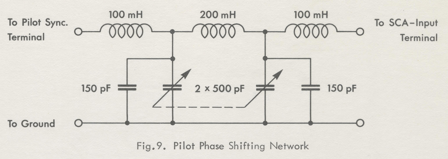
Nell’inventario D del 1956, in data 7 giugno 1960, al n° 1800 si legge: “Fondazione Carlo e Giuseppe Piaggio – Genova.  Contatore elettronico HP mod. 522. Destinazione Radiotecnica”.
All’indirizzo:
https://www.hpl.hp.com/hpjournal/pdfs/IssuePDFs/1952-11.pdf
si può trovare l’Hewlett-Packard Journal Vol. 4 No. 3  del novembre 1952. Il cui titolo è: “A New 100 KC Counter for Use in Electronics and Industry”.
Noi  abbiamo preferito riportare una parte del manuale di istruzioni poiché le figure, opportunamente elaborate, sono meglio definite.
Abbiamo diviso il testo in due parti a causa della sua lunghezza e del numero di foto e figure.
Abbiamo deciso inoltre di omettere il capitolo “Maintenance”, ma ne abbiamo riportato le figure.
Il testo prosegue dalla prima parte.
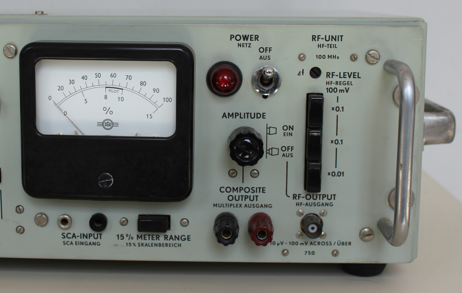
§§§
«2-4 APPLICATIONS
Frequency Measurements
Measurement of frequency is a basic function in counters. Such measurements as oscillator calibration, oscillator drift with time, or drift with line voltage may be made. Frequency response characteristics of tuned circuits, band pass filters, etc. , can be plotted. Some specific frequency measurement applications are described below.
Repetition Rate of Pulses
The repetition rate of pulses is merely counting the pulses for a. standard time. The input of the counter is direct couple d and adjusted to trigger at zero volts. Since a pulse is essentially all positive or all negative from a reference voltage, it may be necessary to introduce some dc bias to enable the pulse to cross the zero axis. With this in mind repetition rates can  be measured in the same manner as any other frequency.
Tachometry
There are a number of transducers available for tachometry measurements. The hp Mode1 5063 is 9, photoelectric tachometer head and the hp Model 508A is a 60 tooth magnetic tachometer. The Model 508A is mechanically connected to the shaft being measured and produces 60 output pulses per revolution. An indication of rpm is given directly when the output frequency of the tachometer is measured. With a 1 second gate time, an accuracy  of ± 1 rpm is obtained. Using a 10 second gate time ± 1/10 rpm accuracy may be obtained. The Model 506B photoelectric tachometer head is designed for use where mechanical linkage is impractical. The light source and phototube assembly should be adjusted  so that the light reflected from the rotating member will enter the phototube. The number of pulses or counts per revolution will depend upon the design of the rotating member. Alternate black and reflecting strips may be placed on the rotating shaft or disc and the speed will be:
speed (RPM) = ( Counter indication × 60) / ( Number of reflecting strips × Gate time in sec.)
Pressure Measurements
The vibrating wire type transducer is a pressure-sensitive element with an associated feedback amplifier.  Its output is a frequency which is determined by the pressure exerted on the vibrating wire cell and has a resolution of about .02 percent. The output of the feedback amplifier is connected to the counter to read frequency. Such transducers can be used in remote locations. Since the indication is a single frequency, no alteration  of information can be caused by transmission. Similar units can also be obtained for indicating temperature.
Extended Gate Time
It is sometimes desirable to measure a signal for a longer time than provided by the counter in order to obtain an average of fluctuating signal or to obtain greater accuracy. This may be done on either frequency or period measurement. The MANUAL GATE switch, when OPEN, prevents the timing pulses from closing the gate. If on frequency measurement a five-second gate time is desired, the MANUAL GATE switch should be closed some time between the 4th and 5th second after counting has begun. Then at exactly 5 seconds time the next timing pulse will close the gate.
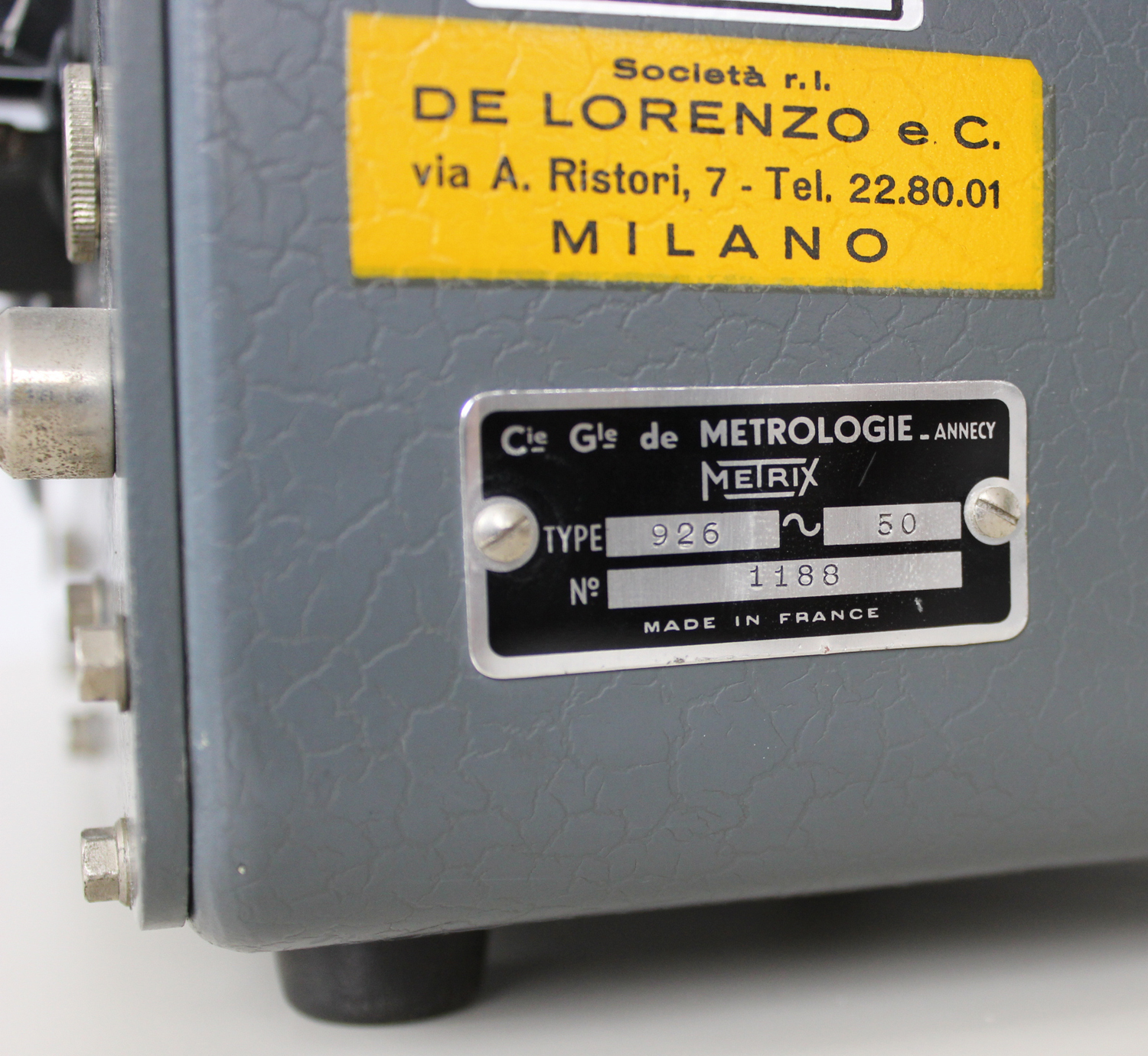
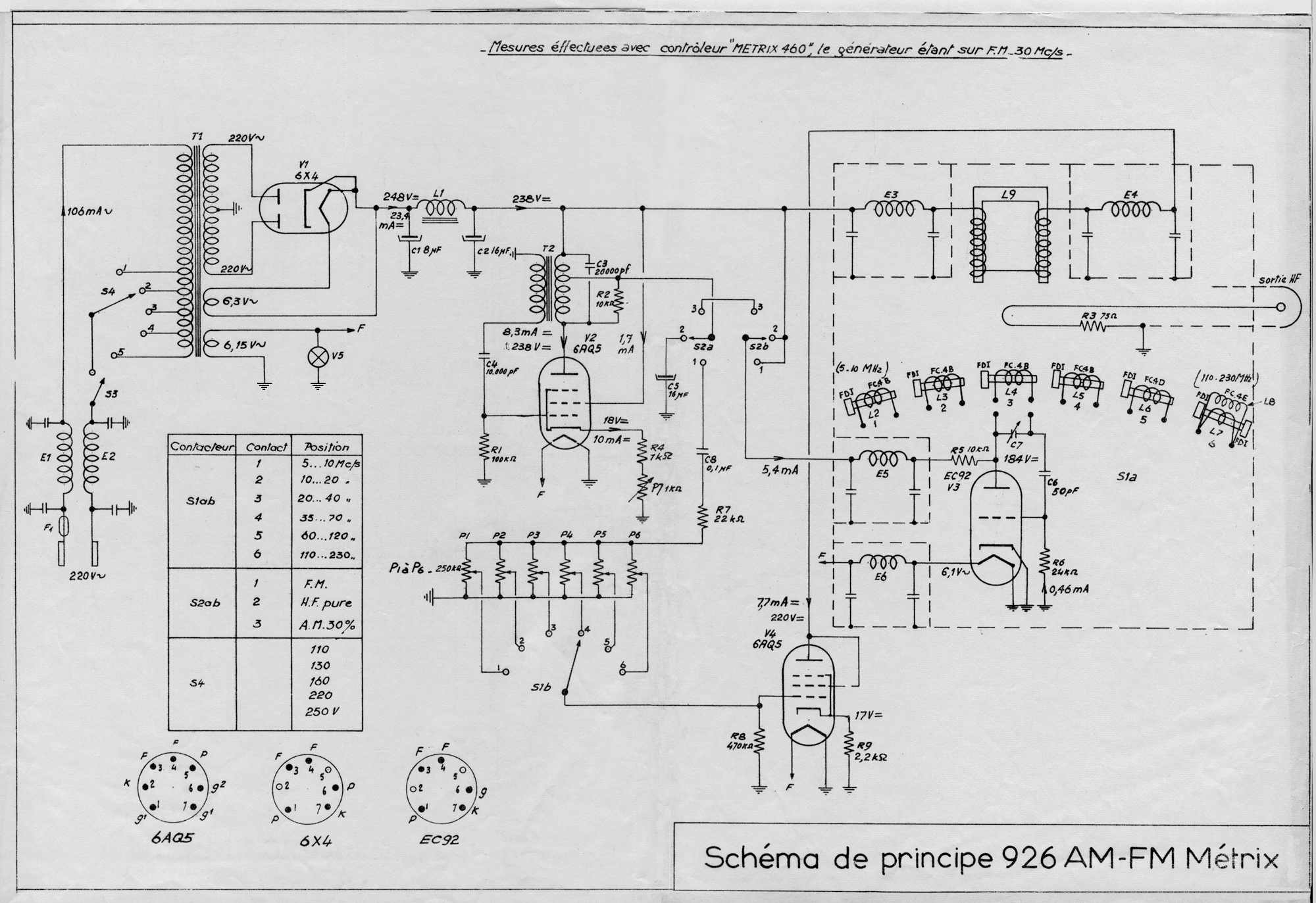
Then:
Freq. in cps = [total number of counts] / [gate time (sec.) ]
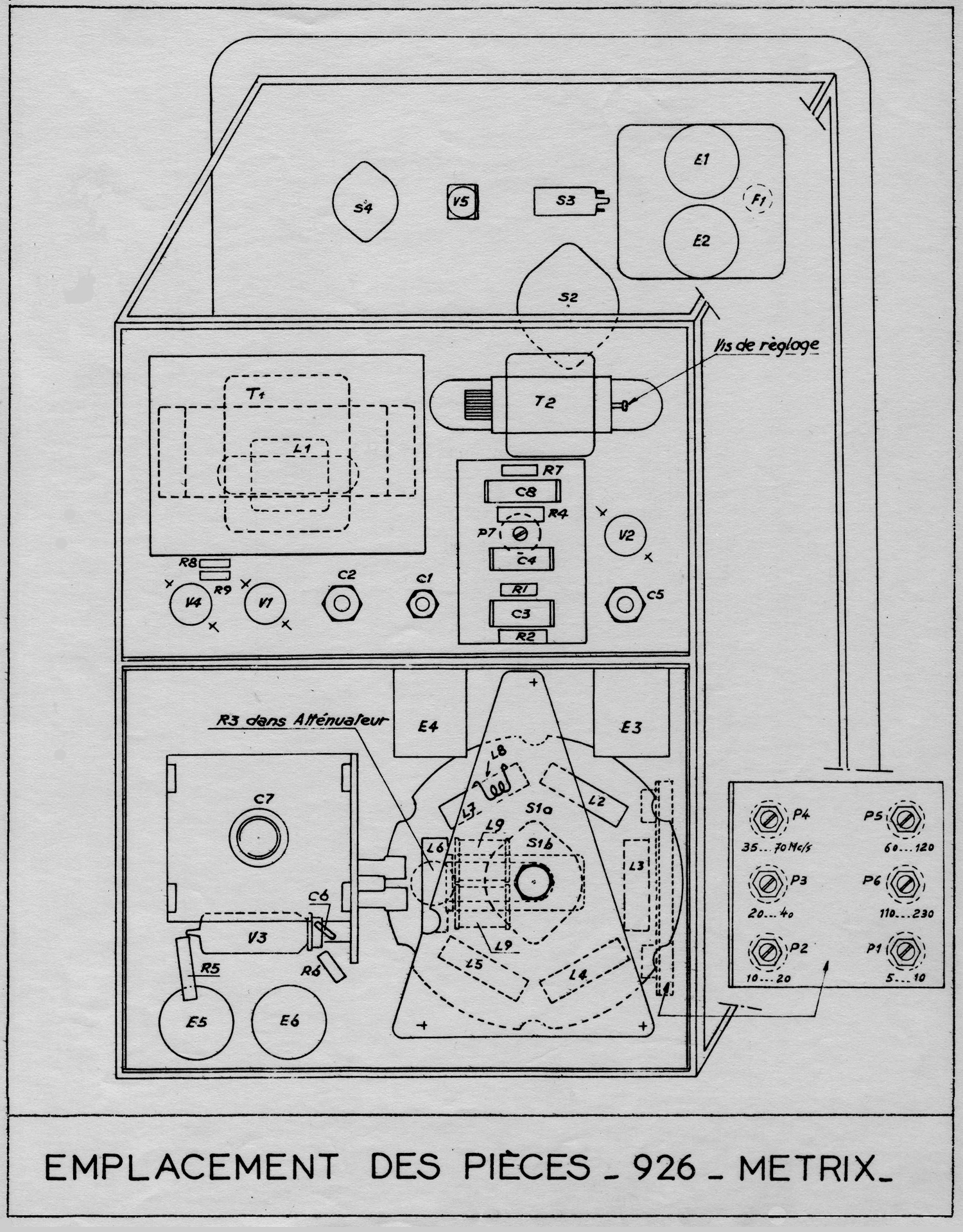
Since with a longer gate time the total count increases, the ± 1 count error decreases. Thus for a 5-sec. gate, for example, the ± 1 count error is 1/5 that of a 1-sec. gate. The number of periods being measured can also be extended by using the MANUAL GATE switch in a similar manner.
Frequency Ratio
The period of a wave generally is measured in terms of time. If the TIME UNIT switch is turned to EXT. the period may be measured in terms of another frequency, and the displayed count will be the ratio between the two frequencies. If the lower of the two frequencies is connected to INPUT, the higher of the two connected to EXT., and the FUNCTION SELECTOR set at PERIOD, frequency ratios from 1:1 to 100,000:1 may be read. With FUNCTION SELECTOR set at 10 PERIOD AVERAGE, ratios may be read from .1:1 up to 10,000:1. If it is desired to measure larger ratios, a mechanical register may be connected to the COUNTER OUTPUT to extend the range.
Time Interval Measurements
Many time interval measurements are possible with the Model 522B, the basic requirement being an electrical impulse at the beginning and end of the desired time interval. This impulse may be generated by any one of a number of specialized transducers, switches, phototubes, etc.
The Hewlett-Packard Journal, Vol. 5, No. 1-2, is devoted to time interval measurements with the Model 522B. It discusses a marker generator that may be of value when making time interval measurements. When making time interval measurements on a complicated waveform, the marker will be helpful in setting the trigger level controls correctly. Contact the Hewlett-Packard Company if you desire any further details on time interval measurements or the marker generator.
CAUTION
When mechanical contacts of any kind (relay, switches, etc.) are used to generate impulses for time interval measurements, precautions must be taken. Mechanical contacts are subject to contact bounce which produces a very irregular impulse as indicated in Figure 2-4. This type of pulse will not trigger the counter at the desired time and under these conditions it is impossible to make accurate or consistent measurements. When mechanical contacts are used to trigger the counter, the impulse from these contacts should be viewed on a wide band oscilloscope. Any irregularities that are present may then be taken into account.

Phototubes
Photoelectric transducers are used where it is impossible or impractical to use mechanical connections for the desired measurement. A 90-volt phototube polarizing voltage is available at the rear of the instrument. The output of the phototube may be connected to either the START or STOP input of the counter through a coupling capacitor. Since these are direct-coupled inputs, it is desirable to include a blocking capacitor between the phototube and the instrument input.
Phase Shift Measurement
The phase difference between two waveforms having the same frequency may be measured in terms of time or electrical degrees. Direct measurements in degrees require using an external source, having a frequency that is 360 times that of the waveform being measured, as the TIME UNIT. (This voltage is applied at the EXT. input connector.) To make phase measurements the instrument is set up as follows:
1.FUNCTION SELECTOR on TIME INTERVAL.
2.TRIGGER INPUT on SEP.
3.MANUAL GATE closed.
Connect the two waveforms to the STOP and START TRIGGER INPUTS, set both TRIGGER LEVEL VOLTS controls at approximately zero both TRIGGER SLOPE switches positive. Note the count. Switch both TRIGGER SLOPE switches to negative and note the count. If these two counts are not equal, adjust the START TRIGGER LEVEL VOLTS control until equal counts are obtained with both TRIGGER SLOPE switches positive and both negative.
Phase Shift (degrees) = 360 × F × {[count (milliseconds)] / 1000}
Where F is the frequency of the waveform being measured. This is the number of degrees the START waveform leads the STOP waveform. If an external TIMEUNIT is used that is 360 times the frequency of the measured waveform, the count will be the number of degrees the START waveform leads the STOP waveform and no calculations will be required. Maximum accuracy is obtained when the instrument is triggered at or near the zero axis crossing of the sine wave. The two counts will be equal when the START and STOP channels are triggered the same number of electrical degrees from the zero axis crossing of each waveform. This measurement is explained as follows:In the illustration T1 = T2 since we have specified equal counts with both TRIGGER SLOPE switches + and both -. Because of the symmetry of the waveforms a1 = a2 and b1 = b2.
SECTION Ill
THEORY 0F OPERATION

3-1 INTRODUCTION
This Section describes the electrical operation of the circuits of the 522B Electronic Counter. First the overall operation of the instrument is explained with reference to the block diagrams in Figure 3-1 and 3-3, then the operation of important circuits is described in detail. The material in this section is as follows:
3-2 Overall Circuit Operation
3-3 Time Base Section
3-4 Phantastron Frequency Dividers
3-5 Decade Frequency Divider
3-6 Amplitude Discriminator
3-7 Signal Gate Section
3-8 Signal Gate
3-9 Gate Control Binary
3-10 Display Time Circuit
3-11 Reset Circuit
3-12 Time Interval Input Circuit
3-13 Power Supply
3-2 OVERALL CIRCUIT OPERATION
The 522B Electronic Counter consists of the basic circuit sections shown in the block diagram in Figure 3-3. A signal applied to the 522B INPUT connector is fed through an amplifier and shaper to the Counted Signal Gate. The essential part of the signal, the frequency, goes through the shaper unchanged, but since this waveform is used to operate decade counting  units, it must be changed to a fast-rise, constant-amplitude pulse to assure positive counting.  The Counted Signal Gate V101A conducts the input signal to the indicating counters while a measurement is being made, and blocks the input signal while the answer is being displayed. While the Signal Gate is open, V406 acts as a normal amplifier; when closed it acts as an open circuit to the input signal. The Signal Gate is opened and closed by precision signals initiated in the Time Base Section which actuate  Gate Control Binary V103 and produce a large fast, on-off pulse to operate the Signal Gate. The first signal from the Time Base Section causes the Gate Binary to open the Signal Gate; the second signal from the Time Base causes the Gate Binary to close the Signal Gate. So long as signals come from the Time Base, the Signal Gate will continue to be opened and closed. Timing Signal Gate V102 conducts the start, and stop timing signals from the Time Base to the Gate Binary while a measurement is being made. V102B blocks start timing signals and prevents a new count from starting while the answer to the previous count is being displayed. Timing Signal Gate V102B is opened and closed by signals from the Display Time Circuit. The Display Time Discriminator either opens and closes the Timing  Signal Gate automatically at regular intervals, or manually by the front-panel RESET button. When set for automatic operation, the Display Time Circuit is operated by signals from the Gate Binary; when the Gate Binary closes the Signal Gate, the Display Time Circuit closes the Timing Signal Gate for the time selected by the DISPLAY TIME control. The next timing signal will not reopen the Timing Signal Gate and start another count before the desired display time has been completed. When the display time is over, the Display Time Circuit reopens the Timing Signal Gate and the next timing signal opens the counted  Signal Gate to start another measurement. Whenever the Gate Binary opens the Signal Gate to start a new measurement, it first operates the Reset Circuit to return the counters to zero, so the new count will begin at zero instead of being added to the previous count. The Reset Thyratron, upon receiving a negative pulse from the Gate Binary, generates a large, fast positive pulse which is applied to the reset circuit of each of the counters. The signal to be counted is fed to six indicating plug-in counting units connected in cascade. The output of the first unit connects to the input of the second, and so on. Each cycle of the input signal advances the count of the first (units) counter by one numeral. Each time the number on the first counter is advanced from 9 to 0 it puts out a pulse which advances the count on the second (tens) counter by one number, and so on through all six units. When the Counted Signal Gate is closed, the indicating counter units display the number of the last cycle received. Thus, the number of cycles displayed after opening the Signal  Gate for exactly 1 second indicates the frequency directly in cps.
3-3 TIME BASE SECTION
The Time Base Section, supplies six standard frequencies: 100, 10 and 1 kilocycles, 100, 10 and 1 cycles per second. The Time Base consists of a crystal-controlled, 100-kc oscillator, a series of five 10 to 1 phantastron frequency dividers, and a plug-in decade divider. The plug-in decade dividerdivides the phantastron frequencies from the Time Base by 10 during frequency measurements and the input signal frequency by 10 during 10 PERIOD average measurement. The same high accuracy obtained from the crystal oscillator is also obtained with all divided frequencies when the circuits are in correct adjustment. The internal frequency standard for the 522B is a crystal-controlled, 100 -kc, modified Pierce or Colpitts oscillator. The crystal has a low temperature  coefficient and is enclosed in a temperature controlled over to obtain a frequency stability of better than ten parts/million/week. The phantastron frequency dividers and the Decade Divider plug-in unit are described below.
3-4 PHANTASTRON FREQUENCY DIVIDERS
The five standard gate times, .001, .01, 0.1, 1.0 and 10 sec, and two frequency units, milliseconds and seconds are obtained by dividing the 100-kc crystal-controlled frequency in steps of 10. Five 10:1 phantastron frequency dividers connected in cascade so that each divides the output of the previous one to produce standard frequencies of 10 kc, 1 kc, 100 cps and 10 cps. The operation of each divider is the same; only the value of one capacitor in each subsequent divider circuit is changed to obtain a ten-times longer time constant. The shapes of the output waveform from the dividers are similar, large unsymmetrical positive pulses. Division in a phantastron circuit is accomplished by adjusting the time constant of the circuit so that one period of phantastron operation lasts nine cycles of the input frequency actually a division of time. During the period of operation the phantastron is not affected by subsequent input cycles. After the period of operation, the phantastron is returned to its original state, ready to be triggered by the next input cycle. Consequently, the phantastron puts out one pulse for each ten cycles of input frequency; but note that it divides by 10 only at the one frequency – at other frequencies, if not readjusted, it divides by another factor, always producing pulses having practically the same period, regardless of the input frequency. To prevent any of the nine intermediate input cycles from prematurely operating the phantastron, the input signal is fed through a diode gate (V109A in Fig. 3-2) which blocks input cycles during the phantastron cycle. The blocking is accomplished by connecting the diode plate to the plate of the phantastron V110, and biasing the diode cathode a few volts below the plate. When the phantastron plate voltage, and thus the diode plate voltage, is high, the diode gate is open and the input signal is passed to the phantastron. When the phantastron is triggered by an input signal, its plate voltage drops and cuts off the diode, thus closing the gate. The phantastron plate voltage remains down (and the gate closed) during nine periods of the input frequency. At the end of its cycle the phantastron plate voltage rises, the diode gate is opened and the next (10th) cycle triggers the phantastron. The switching action in the phantastron circuit is as follows:
Refer to Fig. 3-2. Phantastron tube V110 is a special pentode in which the suppressor grid is tightly wound and can be used as a second control grid for the plate current, but not for the screen current. This feature makes it possible to switch the cathode current from plate to screen and vise versa. In this circuit the initial stable state has current going to the screen, 0 volts between control grid and cathode, and the cathode is 25 volts positive. The suppressor grid, being returned to ground, is thus negative, and blocks current to the plate such that cathode current goes to the screen grid. When a negative input pulse is applied to the phantastron control grid, the cathode voltage drops, the negative bias on the suppressor is instantaneously removed and the cathode current switches to the plate. Current continues to the plate until the charge on C206 discharges through the series resistor R210, the control grid voltage returns in a positive direction, cathode voltage following until the suppressor-to-cathode bias is again negative and the plate current cut off. Actually the voltage on the suppressor is maintained constant by voltage divider R211, 212, and 213, while the control-grid and cathode voltage move together as in a cathode follower to affect the shift in suppressor-grid bias. This shift in bias is held by the time constant of timing capacitor C206 and its series resistor R210, the positive charge curve being applied to the control grid of the tube.3-5 DECADE FREQUENCY DIVIDER
This unit is required primarily for dividing input frequencies by ten during 10 PERIOD AVERAGE measurement. It is also used during frequency measurement to divide the STD. GATE TIME timing signals from the Time Base so that STD. GATE TIMES from 0.001 to 10 seconds can be obtained from the standard frequencies of 10 kilocycles to 1 cycle per second obtained from the phantastron dividers. This unit, unlike the phantastron divider, is not sensitive to its operating frequency and will divide by ten at any frequency up to approximately 10 kilocycles. The operation of the decade divider is described below.
The Decade Divider consists of four cascaded binaries  (bistable multivibrator), each triggered by the previous binary. Consequently, the cycles fed to the input are divided by two in the first binary (since the first pulse switches the binary to the opposite state and a second input cycle is required to return it to the original state) and again by two in the second binary (to make a total division by four) and so on, with an expected total division of Sixteen at the out-put of fourth binary. The desired division of ten is obtained by two feedback loops to the second and third binaries so that the eighth input pulse will be reset to the states they would be in had they received14 inpulses at the input. Consequently, after the ninth and tenth input cycles are received, the desired final output pulse is produced. This action is identical to the action of the AC-4A Decade Counter without its indicating lights, and in general the voltages and waveforms are the same.
The basic unit in a decade divider is a bistable multivibrator. The bistable multivibrator has two stable states, A-side conducting, B-side cut off, and vice versa. The circuit remains in either state until a negative pulse is applied to the common plate-load resistor to switch conduction to the opposite side. The grids are biased so that positive pulses will not switch the circuit. A negative input pulse does not affect the tube that is cut off but decreases conduction in the tube that is conducting. This will increase its plate voltage and in turn the grid voltage of the tube that is cut off. This regenerative action continues until conduction has switched from one tube to the other. The input is applied to the common plate circuit for simplicity, and since the plates and grids are interconnected the input signal is also applied to the grids.
3-6 AMPLITUDE DISCRIMINATOR
Amplitude Discriminators are used to develop the fast-rise pulses required to operate subsequent binaries at a certain voltage level on the driving waveforms. For example: a sine wave applied to the input connector for frequency measurement must be converted into constant-amplitude, fast-rise pulses to operate the indicating counter units reliably. Input signals for period measurements must be converted into constant-amplitude, fast-rise pulses for precise opening and closing of the Counted Signal Gate. The essential part of the Amplitude Discriminator, a Schmitt Trigger, produces a large, sharp output pulse regardless of the shape of the signal that triggers. In addition, the discriminator can be adjusted by its sensitivity adjustment so that it will produce the output pulse when the input signal reaches a certain voltage level. Each discriminator is preceded by a differential amplifier so that a substantial trigger operating voltage is assured. The operation of the Schmitt Triggers is described below. A Schmitt Trigger consists of two amplifiers (twin-triode tube), each having both d-c plate-to-grid and cathode-to-cathode coupling from A triode to B triode. The circuit has two stable states; A side fully conducting, B side cut off; B side fully conducting, A side cut off. The circuits remain in either stable state until driven to the switching point by the differential amplifier. The d-c voltage level applied to the A-side grid determines which state the circuit will be in. If the grid voltage is more positive than a certain established level, A side will conduct and B side will not; if more negative than that same level, A side will cutoff and B side will conduct. Each time the A-side grid voltage  crosses this threshold in the opposite direction, the circuit changes state. In practice, the threshold voltage is slightly more positive when moving the grid in a positive direction, and slightly more negative when moving the grid in a negative direction. The range between the two different voltage levels is the hysteresis of the circuit. Hysteresis is the limiting factor on sensitivity since the input voltage must swing through both hysteresis limits to produce an output pulse. The hysteresis of this circuit should be adjusted to give a sensitivity between 0.1 and 0.2 volt.
The manner in which the Schmitt Trigger changes state is as follows:
If A side is cutoff and B side is conducting, and the A side grid voltage is gradually made more positive, a grid voltage will be reached that will cause A side to conduct. When A side begins to conduct its plate voltage drops, which in turn drops the grid voltage of B side, and cuts B side off. As B side cuts off its cathode voltage goes more negative. Since the cathodes are direct coupled, this constitutes positive feedback and further drives A side into conduction until plate saturation is reached. This action is very rapid and when completed, the Schmitt Trigger is in the opposite stable state. It will remain in this state until the voltage level of the A-side grid is moved negatively until the lower hysteresis limit is crossed and A side is cutoff. The above process is then repeated in the opposite direction.3-7 SIGNAL GATE SECTION
The circuits of the Signal Gate Section are shown in the Gating Section and Switching Section Schematic Diagrams at the rear of the manual. In order of signal progress through the section, it consists of the FUNCTION SELECTOR switch circuits which select the desired type of measurement; an Amplitude  Discriminator plug-in unit which shapes the counted signal waveform into sharp pulses without affecting the important information – the frequency; the Counted Signal Gate which permits the signal- to-be-counted to pass to the indicating counters, or blocks it; the Gate Control Binary which opens and closes the Counted Signal Gate; the Decade Counter plug-in units described in the supplementary manual at the rear of this manual; and the Counter Reset and Display Time circuits. Each of these circuits is described separately in other paragraphs in this section.
3-8 SIGNAL GATE
The Signal Gate is a single triode section of a dual-triode  tube. The signal to be counted and the opening-closing control signals are both applied to the control grid of this tube. When the control signal holds the control grid below cutoff, the signal to be counted does not appear in the plate circuit. When the control signal returns the grid to its normal operating voltage,  the Signal Gate is a normal amplifier and the signal to be counted is passed to the indicating counter units. For frequency measurements, the input signal is fed through the gate to the counters, while the gate is opened and closed by precision timing signals from the Time Base Section. For time interval and period measurements the gate is opened and closed by the input signal, while a standard frequency from the Time Base Section is fed through the gate to the counters.
3-9 GATE CONTROL BINARY
The Gate Control Binary, V103A and B opens and closes the Signal Gate by raising and lowering the grid voltage on the Gate tube. In addition, the Gate Binary starts the Reset Circuit just before it opens the Signal Gate, and also starts the Display Time Circuit when it closes the Signal Gate. The Gate Binary is actuated either by precision timing signals from the Time Base Section during FREQUENCY measurement, or by a signal from the INPUT connector for PERIOD and 10 PERIOD AVERAGE measurements, or by the front panel RESET button. The duty of Gate Control Binary is to trigger the Reset Circuit, open and close the Counted Signal Gate and start the Display Time Circuit. The Gate Control Binary is a bistable multivibrator which is triggered by negative pulses. For frequency measurement, the negative trigger pulses to start and stop the measurement are obtained from the Time Base Section and are applied to both sides of the binary.  For time-interval measurements the negative trigger pulses to start and stop the measurements are obtained from the input connectors and can either be applied to both sides of the binary or they can be kept separate, with the start signal going to B side and the stop signal going to the A side of the binary. During automatically repetitive measurements, the negative trigger pulses alternately switch conduction from one side of the binary to the other side. Before a measurement is begun V103A is cut off, V103B is conducting and its low plate voltage cuts off the Counted Signal Gate tube. To begin a measurement a negative pulse applied to the binary cuts B side off, which immediately triggers the Reset Circuit and returns all indicating counter units to 0. Twenty microseconds later, the same signal having passed through a delay line, opens the Counted Signal Gate. The twenty-microsecond delay allows time for the circuits of the indicating counters to stabilize before they begin counting. The subsequent negative trigger pulse applied to the Gate Binary cuts V103A off (returning the binary to its original state), closes the Counted Signal Gate and starts the Display Time Circuit. The negative trigger pulses are coupled into the Gate Binary through two diodes serving as gates to the pulses. The gate to each grid is biased by the voltage at the opposite plate. When A side is conducting, its plate voltage is low and biases the B-side gate so that incoming negative trigger pulses to B side are blocked. Consequently only a conducting side can be triggered. The operation of the gate binary circuit is similar to the binary in the decade divider and decade counters.
3-10 DISPLAY TIME CIRCUIT
The Display Time Circuit determines how long an answer will be displayed before the next count is begun. Display time is started by the Gate Binary when it closes the Counted Signal Gate, and the Display Time Circuit prevents a new trigger pulse from reaching the Gate Binary to and start a new count. This is done by biasing the Gate Binary’s B-side (start channel) diode gate beyond cutoff. The counter will then continue to display the last count until the start-channel diode gate is reopened. The Display Time Circuit’s action begins when the Gate Binary B side fires the Display Time Thyratron as the A side closes the Counted Signal Gate. Display Time Thyratron V107 starts the display time by charging C123 positively and switching Display Time Discriminator V104 so it produces a positive output voltage. The positive output voltage applied to the cathode of Diode Gate V102B, closes the gate and prevents trigger pulses from reaching the Gate Binary. The display holding action continues until C123 discharges through R165 and decreases the grid (pin 6) voltage on Display Time Discriminator V104 and retriggers V104 to produce a negative output voltage. The negative output voltage from the Display Time Discriminator reopens Diode Gate V102B and permits the next negative pulse to operate the Gate Binary and start a new measurement.
3-11 RESET CIRCUIT
The Reset Circuit generates a strong positive pulse which resets all indicating counter units to “0” before each new count is begun. During automatic, repetitive measurements, Reset Thyratron V105 generates this positive pulse when it is triggered by the same positive pulse from the A side of Gate Binary V103 that opens the Counted Signal Gate to start a new count. The pulse to the Signal Gate is delayed twenty microseconds by Delay Line DL 101 to give the counter circuits time to reset and stabilize before they receive the new signals. The manual RESET button generates a positive pulse for resetting the counters by ungrounding the reset wire so that its potential automatically rises approximately 40 volts positive. The positive reset pulse for the counters also resets the decade divider to the beginning of its division cycle so that it will divide the next input signal by ten.
3-12 TIME INTERVAL INPUT CIRCUITS
During time interval measurements, the measurement start and stop input signals are fed to separate, identical Amplitude Discriminators which generate strong trigger pulses as the input voltage levels pass the levels indicated by the TRIGGER LEVEL VOLTS controls. The sharp pulses produced by the Amplitude Discriminators are fed directly to the Gate Control Binary which in turn operates the Counted Signal Gate to make the measurement. The TRIGGER LEVEL VOLTS controls in the START and STOP input circuits determine the input voltage level that will start and stop a time interval measurement by simultaneously attenuating the input signal and applying a negative bias voltage to the Amplitude Discriminators. When the TRIGGER LEVEL controls are set to zero, there is a fixed attenuation of 4 to 1 and no d-c bias on the Amplitude  Discriminator, which triggers as its input signal voltage passes through zero volts. When the TRIGGER LEVEL control is set to +100, there is an attenuation of 20 to 1 and a d-c bias of -5 volts so that the input signal is reduced to +5 volts, just sufficient to override the -5 volt bias and trigger the Amplitude Discriminator.Any d-c voltage accompanying the signal applied to the input connectors will alter the d-c bias and render the control calibrations inaccurate.
3-13 POWER SUPPLY
The power supply section supplies +330 vdc unregulated  at 75 ma, +200 vdc regulated at 80 ma, -105 vdc regulated at 25 ma and -175 vdc unregulated for the circuits of the counter. The positive regulated voltage is obtained from an electronic regulator circuit, V117, V118 and V119 while the negative regulated voltage is obtained from gaseous voltage regulator tube V119. The unregulated voltages are obtained from the power sources for the voltage regulators. The +200 volt regulator is a two stage, direct coupled, feedback amplifier. V117 is the series regulator tube and carries the total load current. V118 controls the resistance of V117 to keep the output voltage constant over a wide range of load currents and line voltage  fluctuations. Any increase in output voltage will make the grid of V118 more positive; this will increase its plate current and in turn decrease the bias on V117. Increasing the bias on V117 increases its resistance and return the output voltage to the original value. A decrease in output voltage will have the reverse effect on the circuit. V119, a voltage regulator tube, supplies a constant fixed bias for V118.»
§§§
Per consultare la prima parte scrivere “522B” su Cerca.
Foto di Claudio Profumieri, elaborazioni e ricerche di Fabio Panfili.
Per ingrandire le immagini cliccare su di esse col tasto destro del mouse e scegliere tra le opzioni.