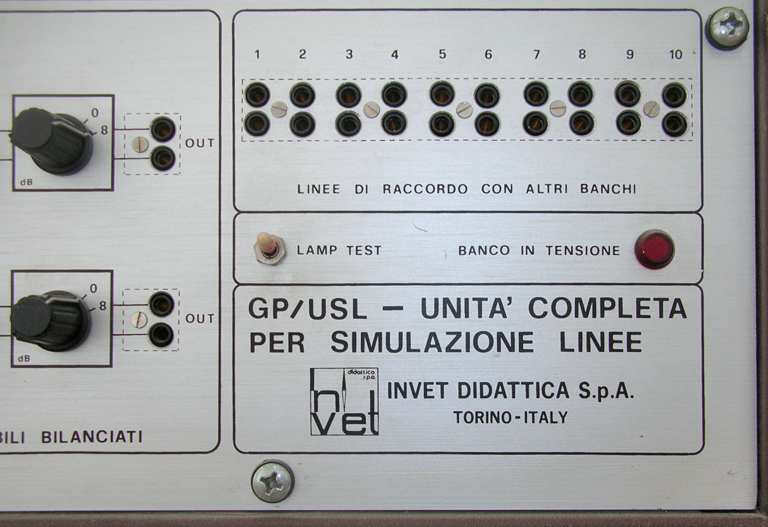
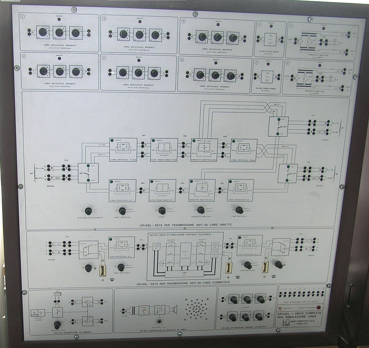
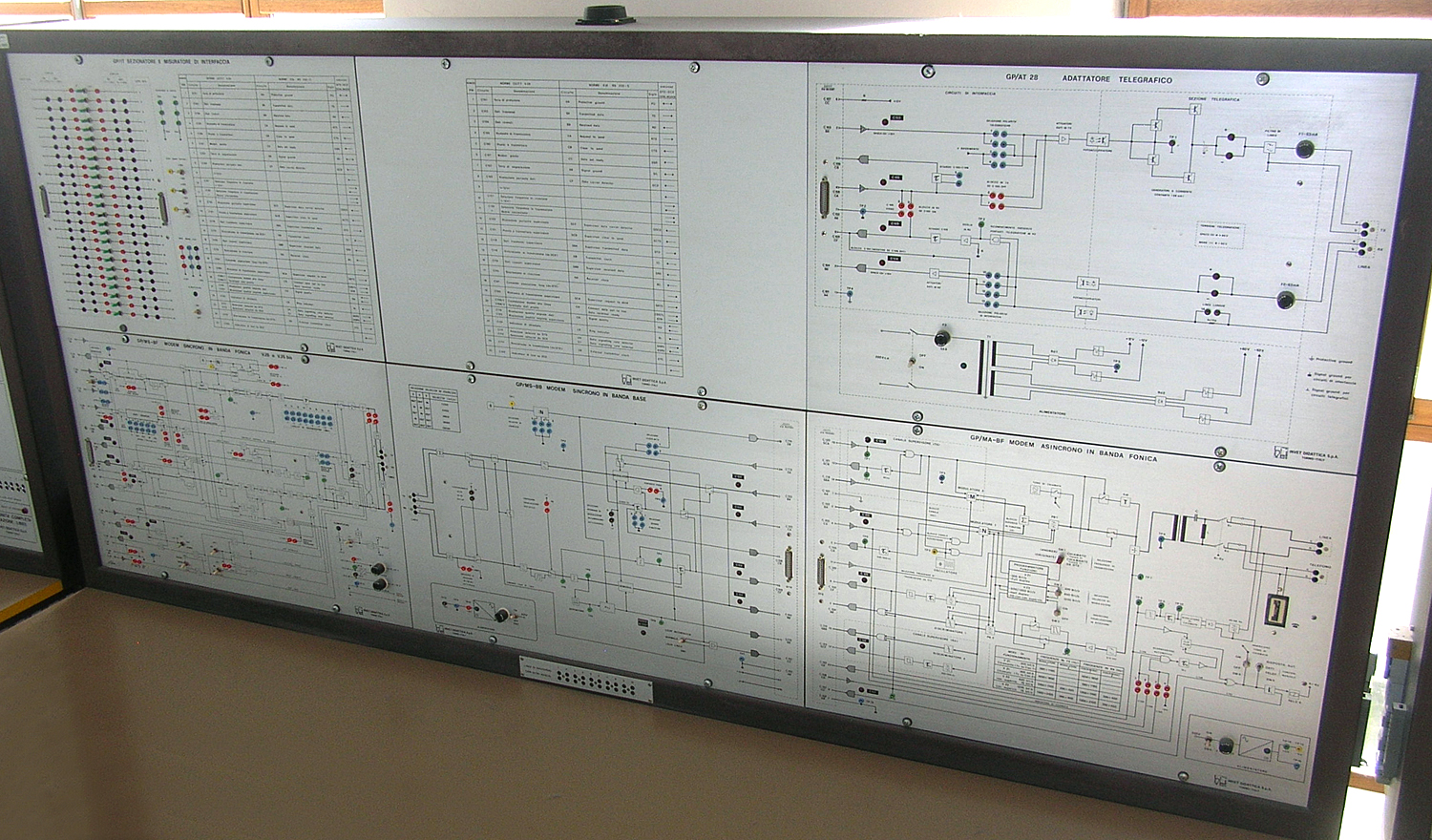
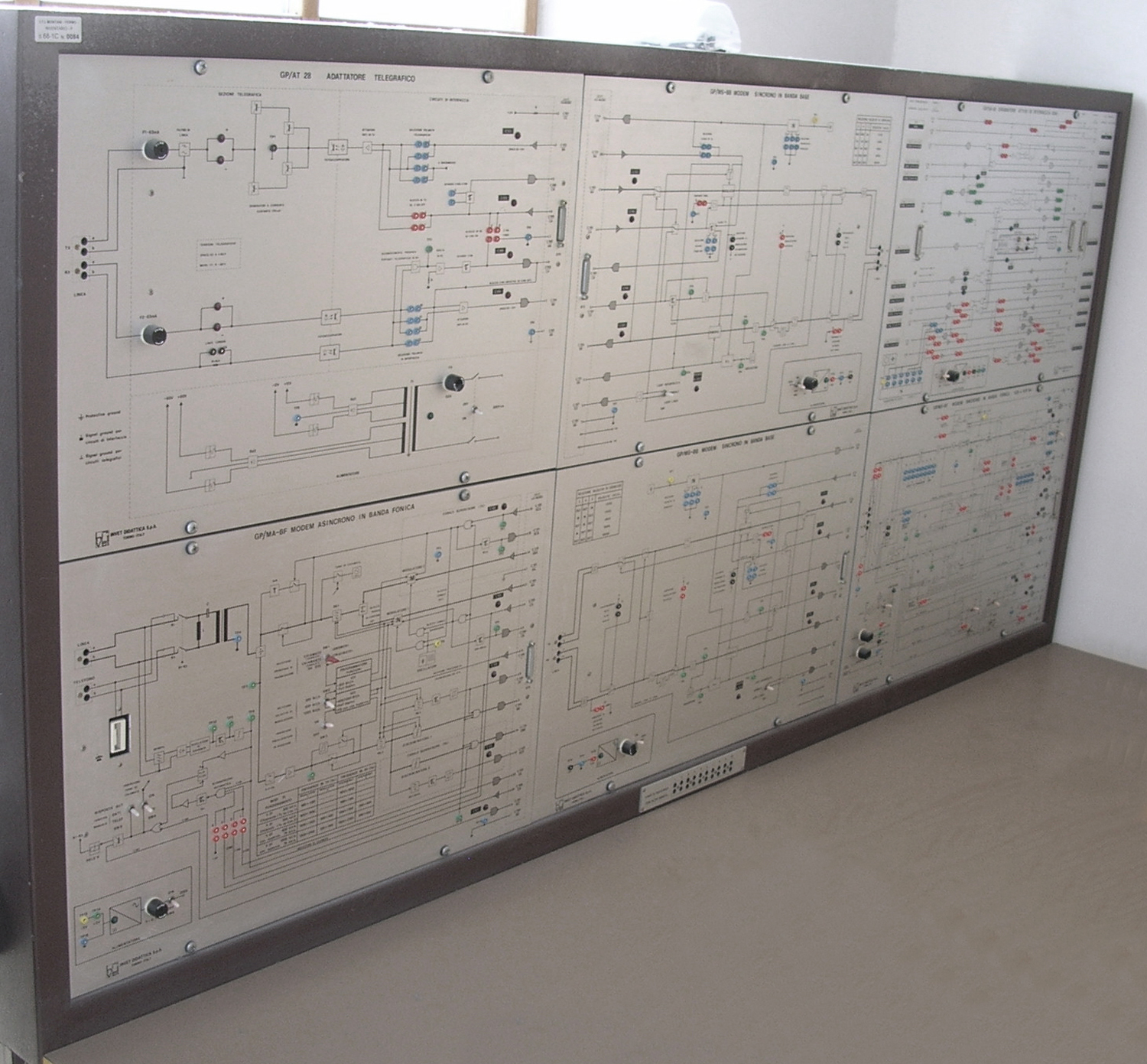
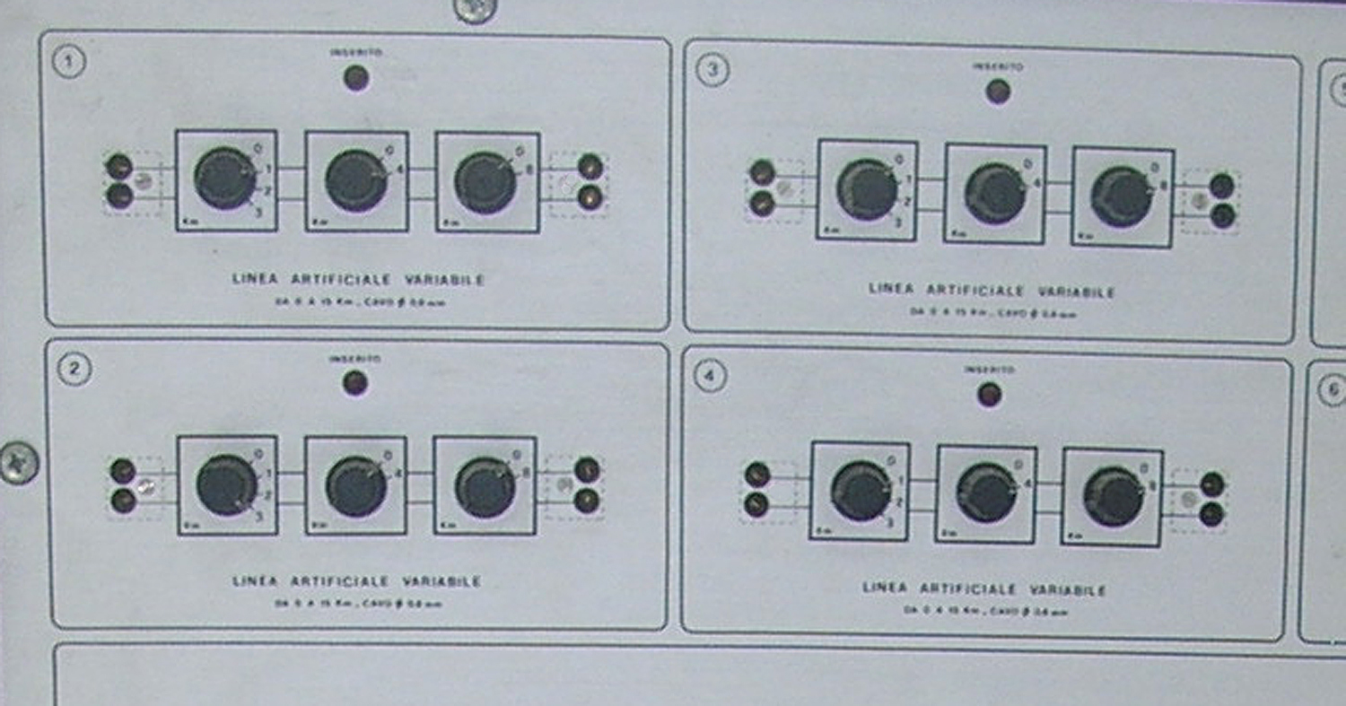
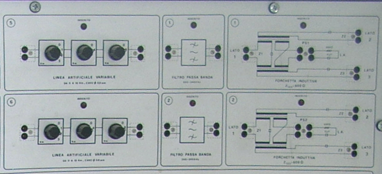
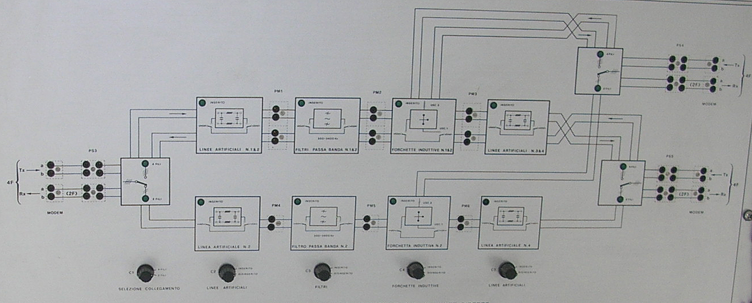
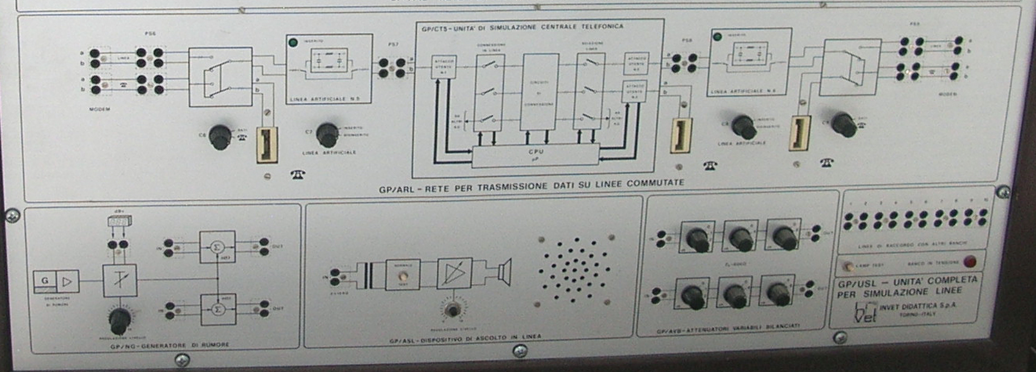
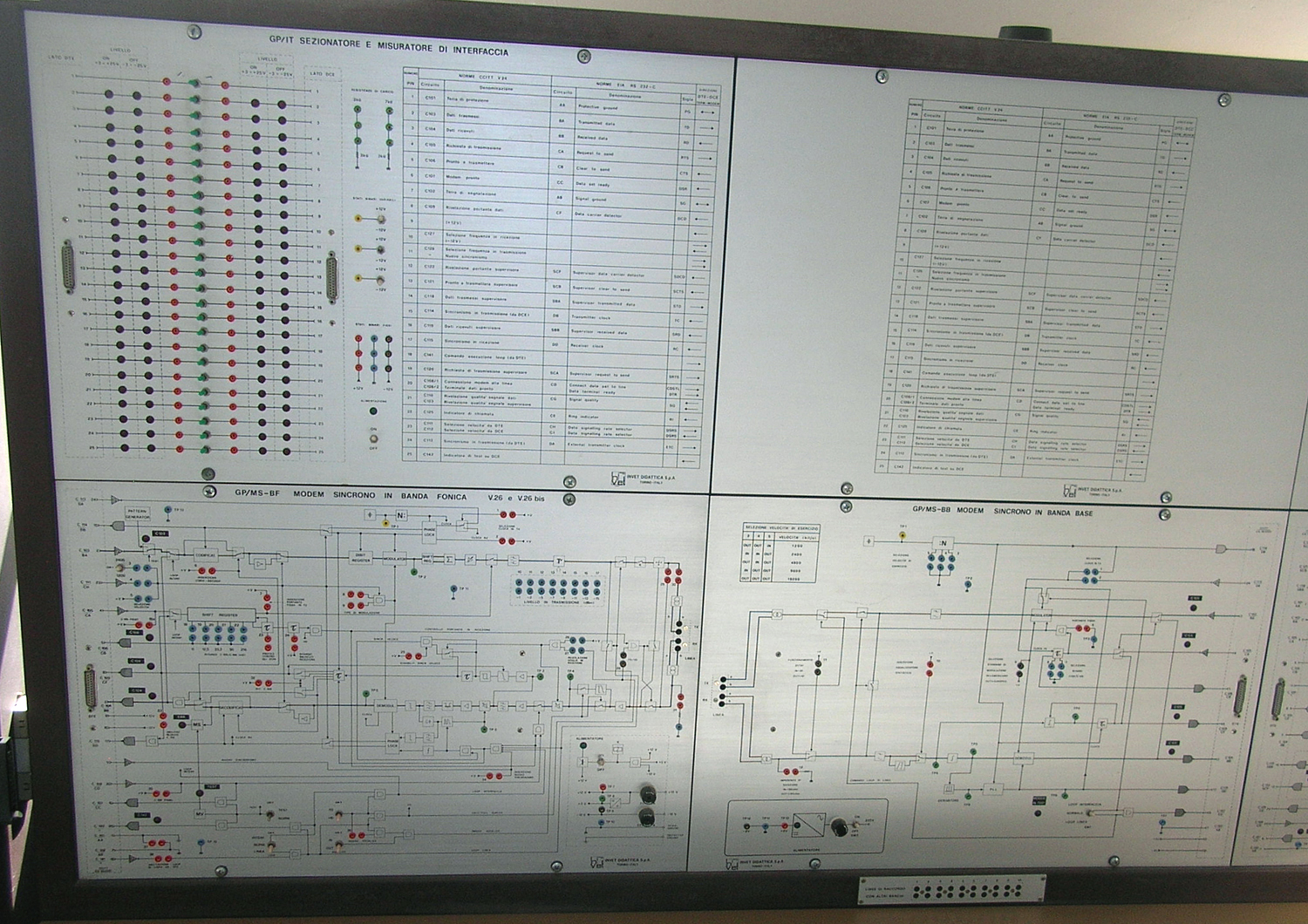
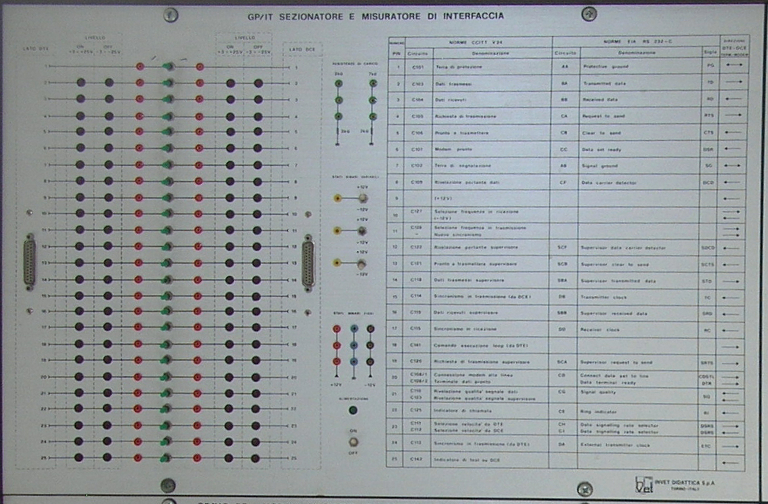
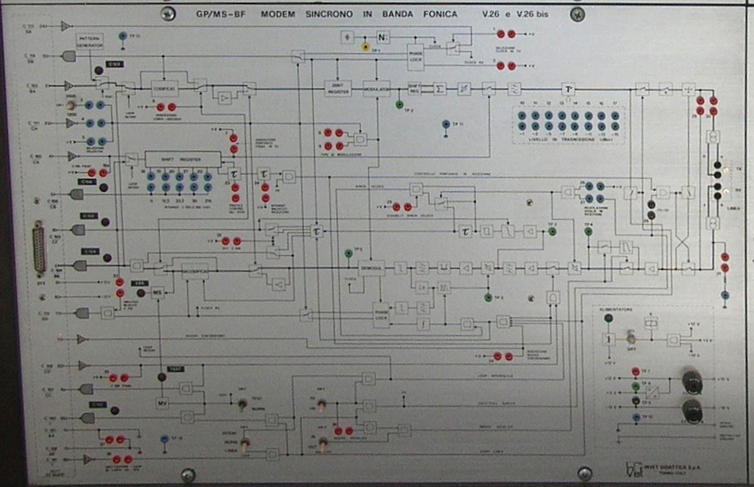
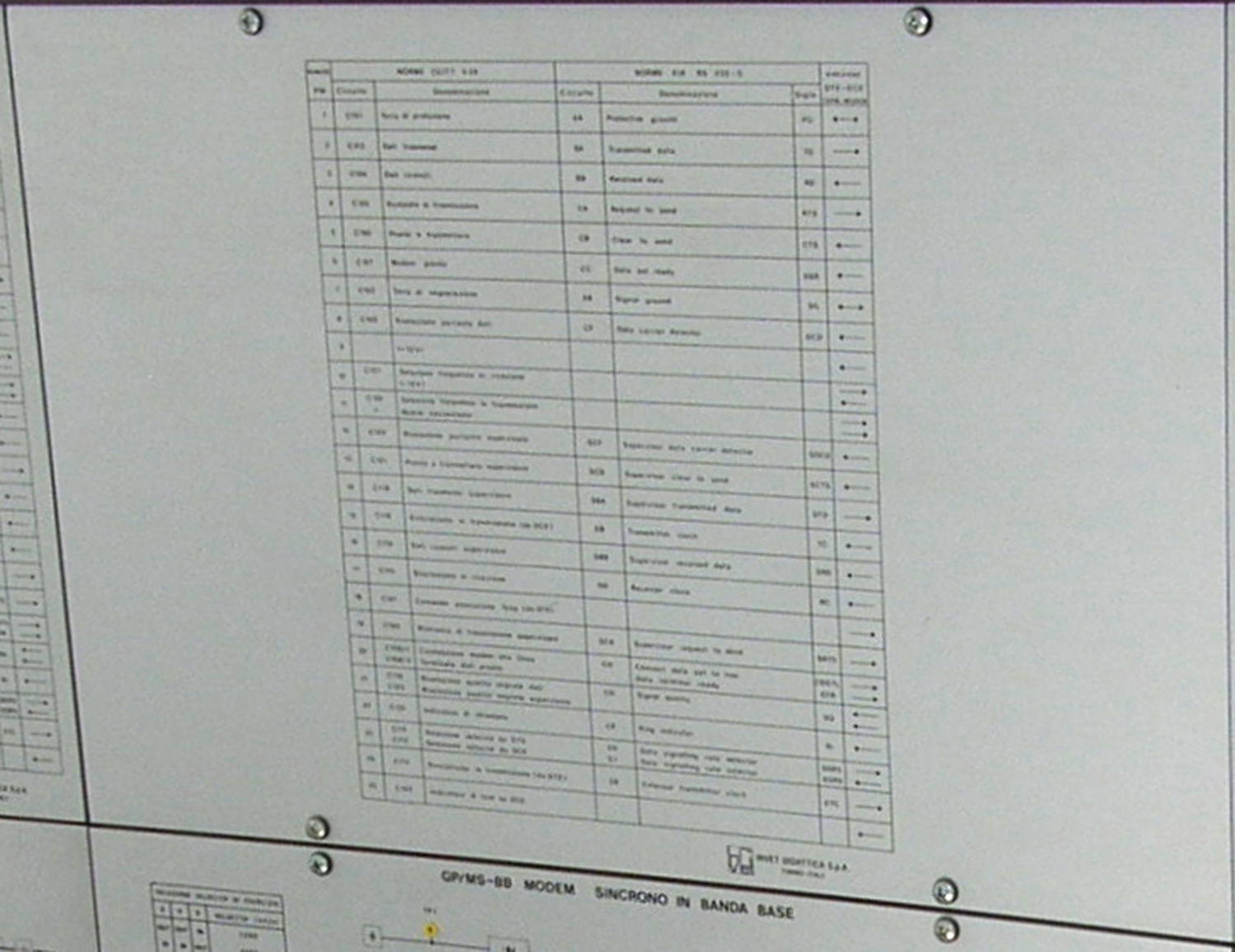
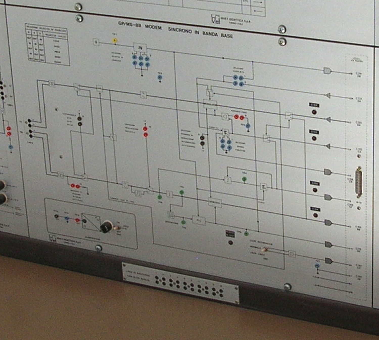
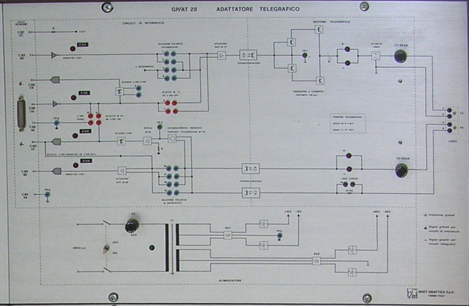
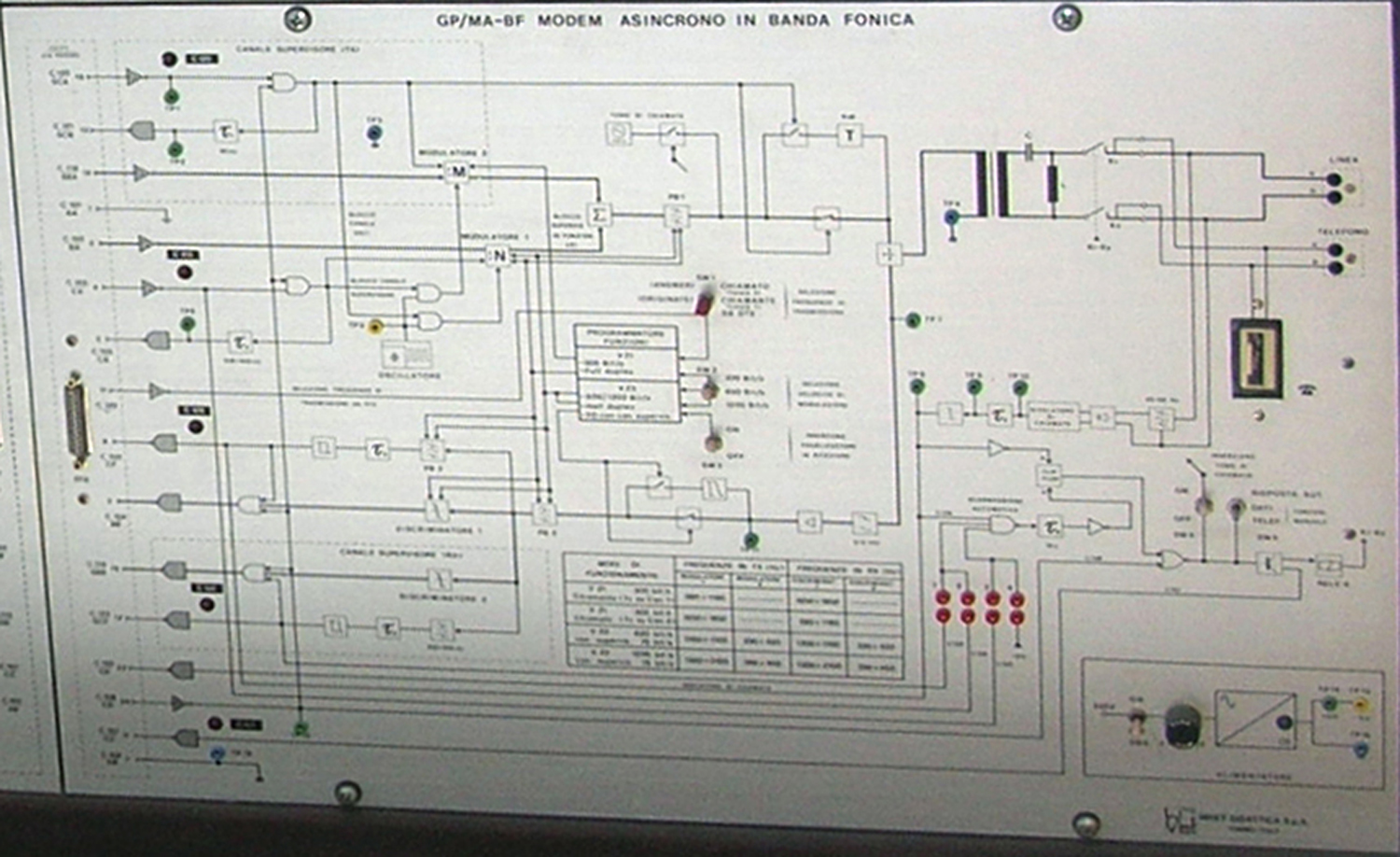
 Simulatori di Linea INVET s.p.a. Torino.
Per ragioni non solo logistiche (2023) non abbiamo potuto né consultare gli inventari, né cercare eventuali documentazioni sparse per i vari ambiti del Triennio (attualmente chiuso), come la vasta Biblioteca e i reparti.
Abbiamo chiesto a diversi insegnanti, che all’epoca erano a conoscenza delle funzioni di queste apparecchiature, ma abbiamo ottenuto scarne informazioni.
Sappiamo vagamente che i simulatori furono acquistati a fine anni Settanta del Novecento; che erano destinati alla Sezione di Telecomunicazioni, che alcuni insegnanti (ora in pensione) parteciparono ad un corso per avere una base di conoscenze, e poco altro.
Se qualche visitatore ha informazioni su questi simulatori è vivamente pregato di scrivere all’indirizzo:
fabio.panfili@live.it .
L’ing. Claudio Profumieri ha fatto del suo meglio per fotografare i tre apparecchi che sono di grandi dimensioni e sono posti in un luogo non certo adatto per eseguire buone foto.
Abbiamo voluto comunque far vedere anche alcuni particolari dei due primi apparecchi, seppur con immagini di bassa qualità.
Elaborazioni e testo di Fabio Panfili.
Per ingrandire le immagini cliccare su di esse col tasto destro del mouse e scegliere tra le opzioni.
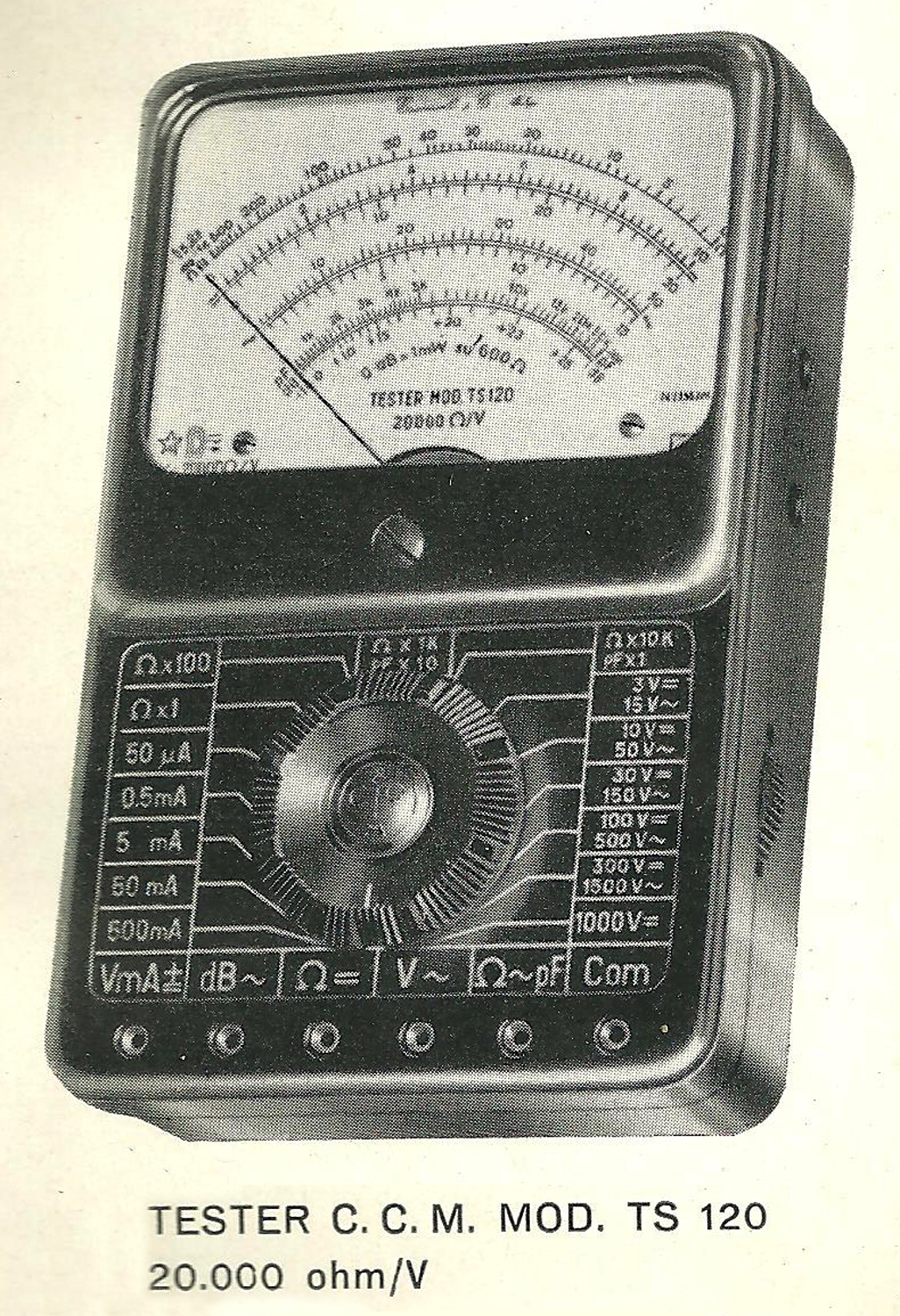
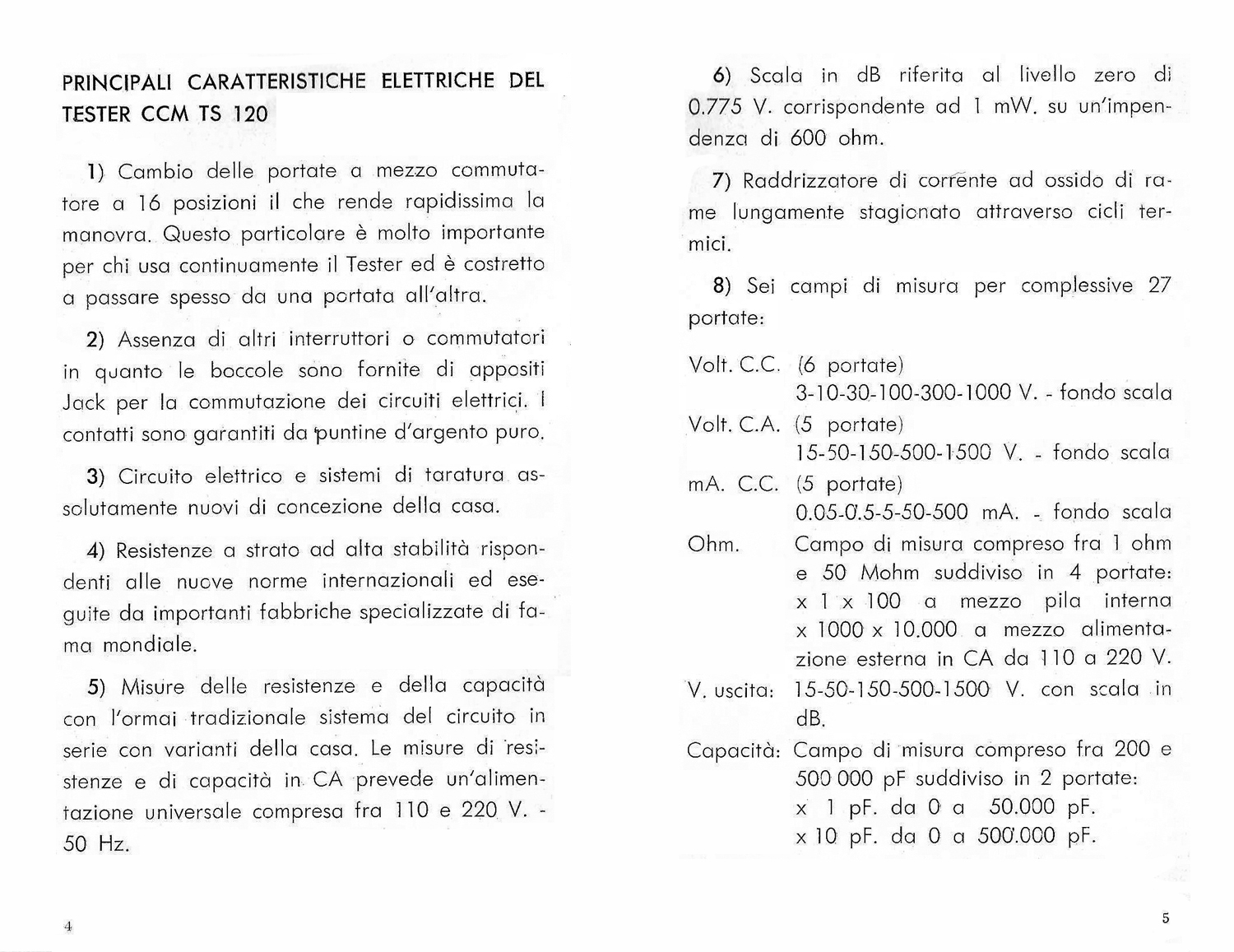
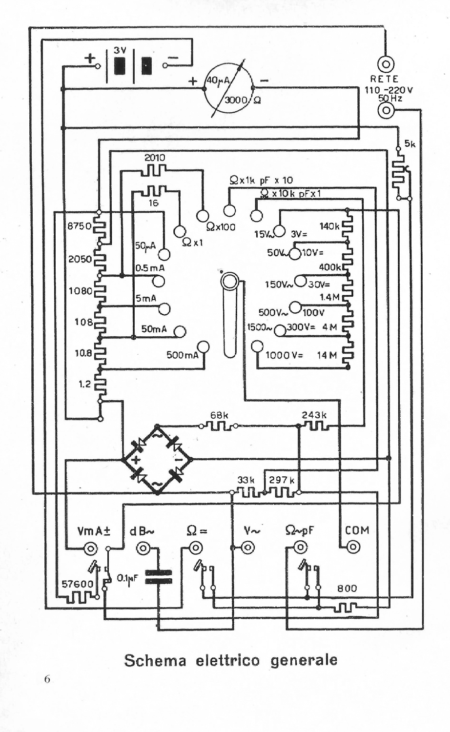
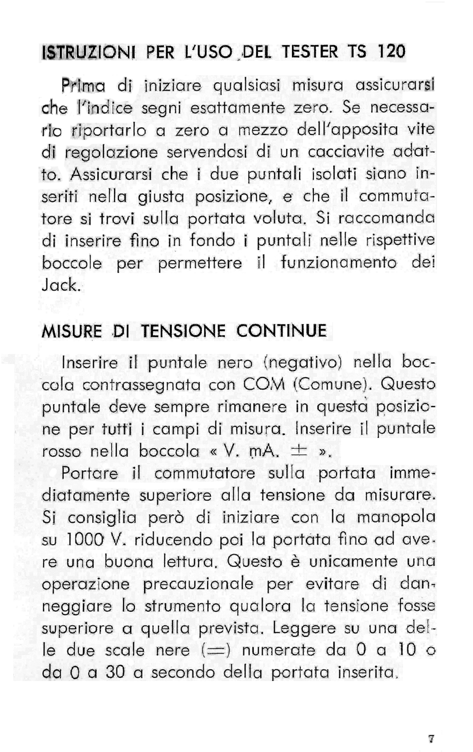
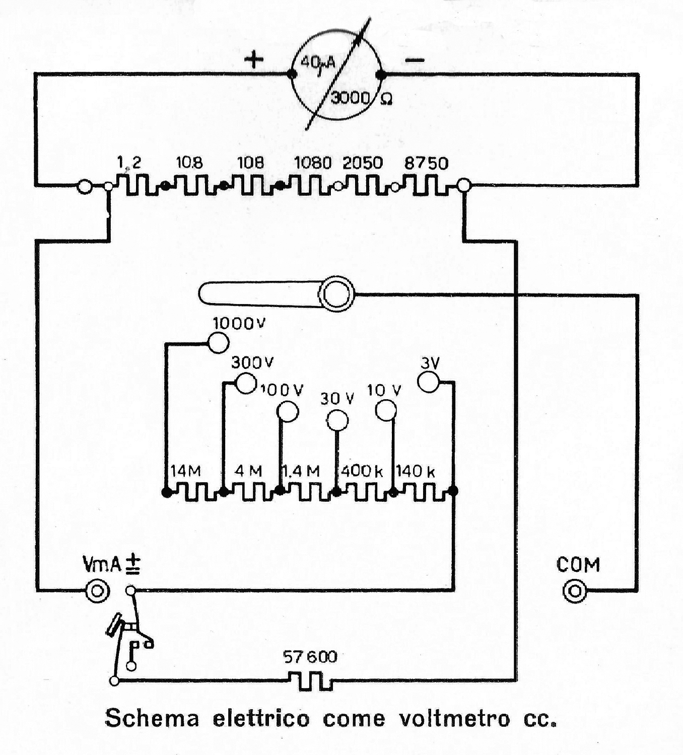
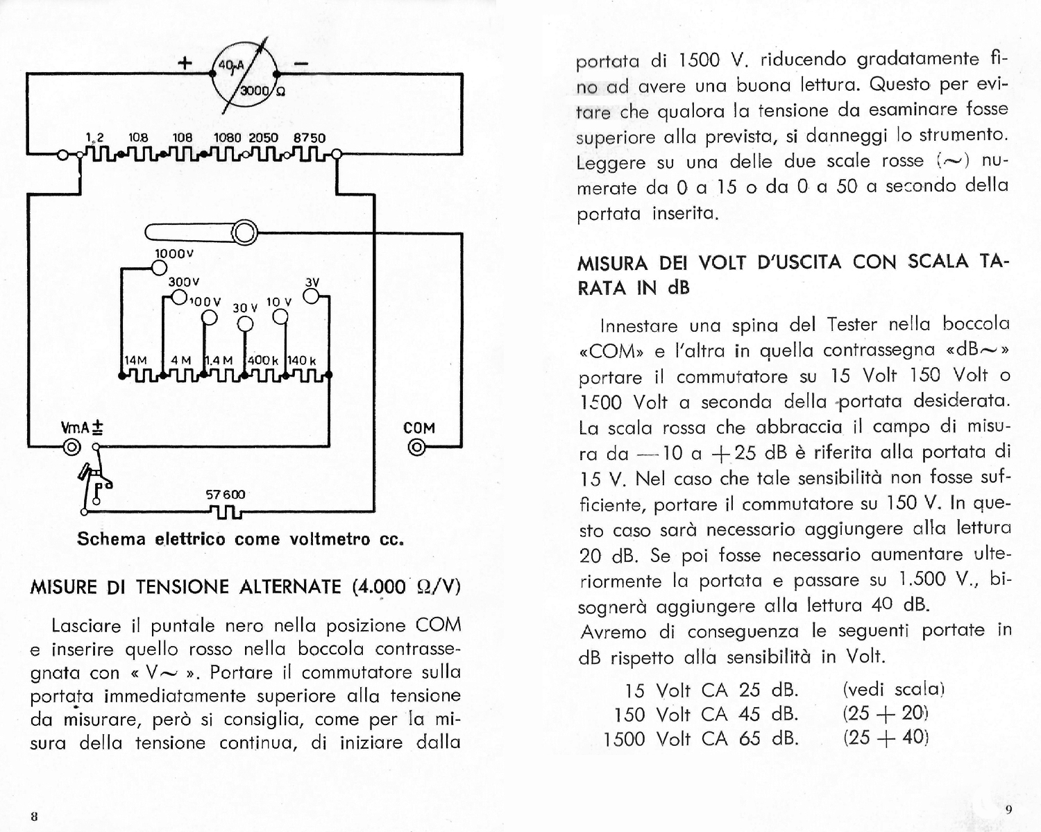
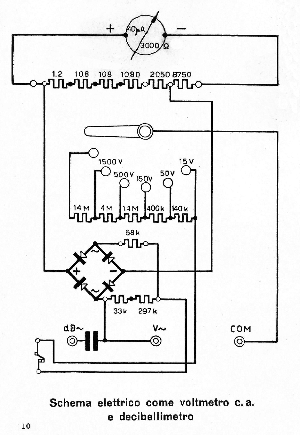
Tester Cassinelli mod. TS 120 Istruzioni d’uso
 Tester Cassinelli mod. TS 120 Istruzioni d’Uso.
Chi scrive possiede un tester Cassinelli mod. TS 120 matr. N° 184649.
Questo strumento fu assemblato nel 1960 come esercitazione scolastica della 3ª A, Sezione Radiotecnica, dal fratello maggiore Antonio (previo acquisto personale dei componenti, per ₤ 15.000).
Il tester, nonostante i numerosi e involontari maltrattamenti avvenuti negli anni ed un uso molto frequente, nel 2024 continua a funzionare egregiamente.
Note storiche di Fabio Panfili
Per ingrandire le immagini cliccare su di esse col tasto destro del mouse e scegliere tra le opzioni.

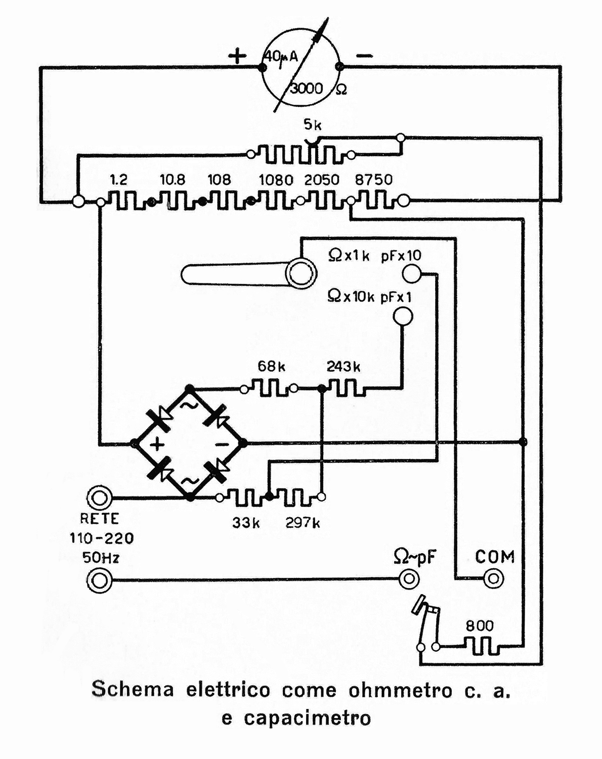

Mavometer Original Gossen D.R.P. 3ª parte
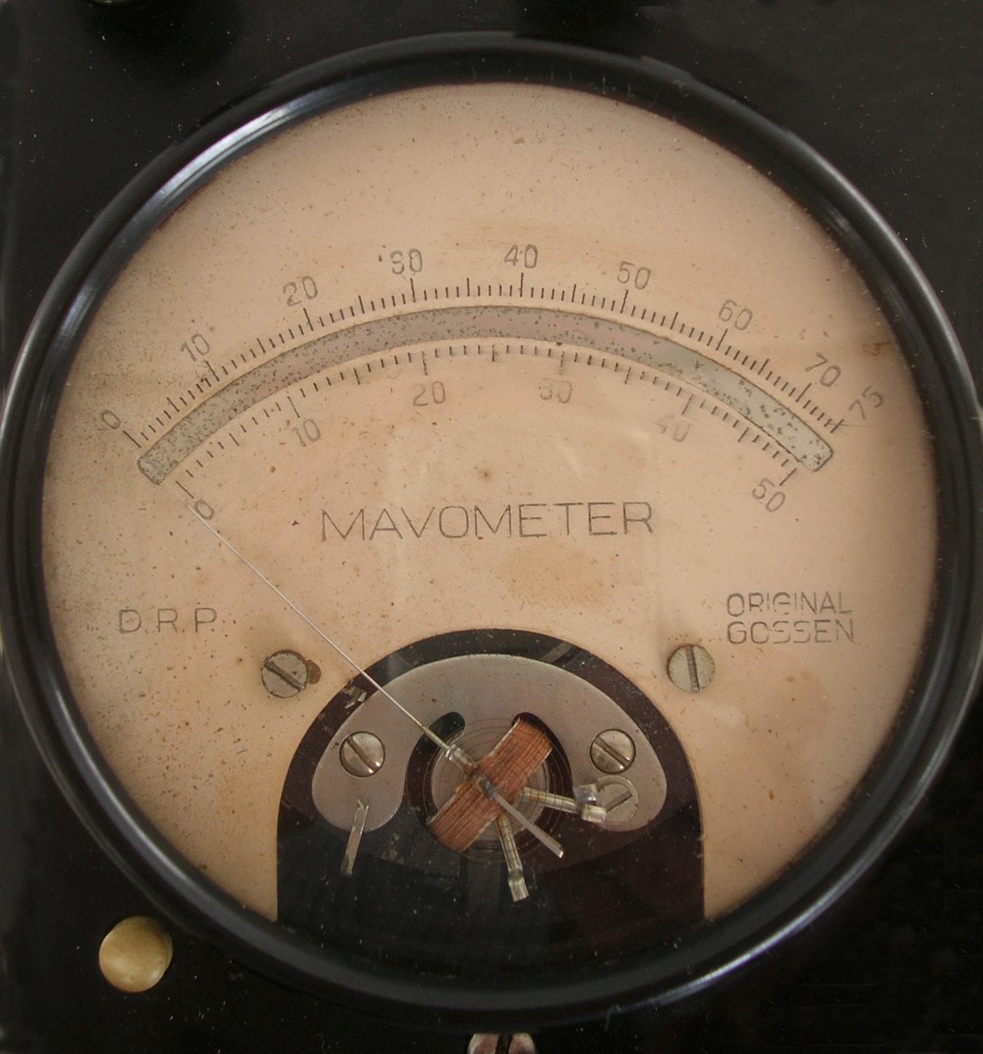
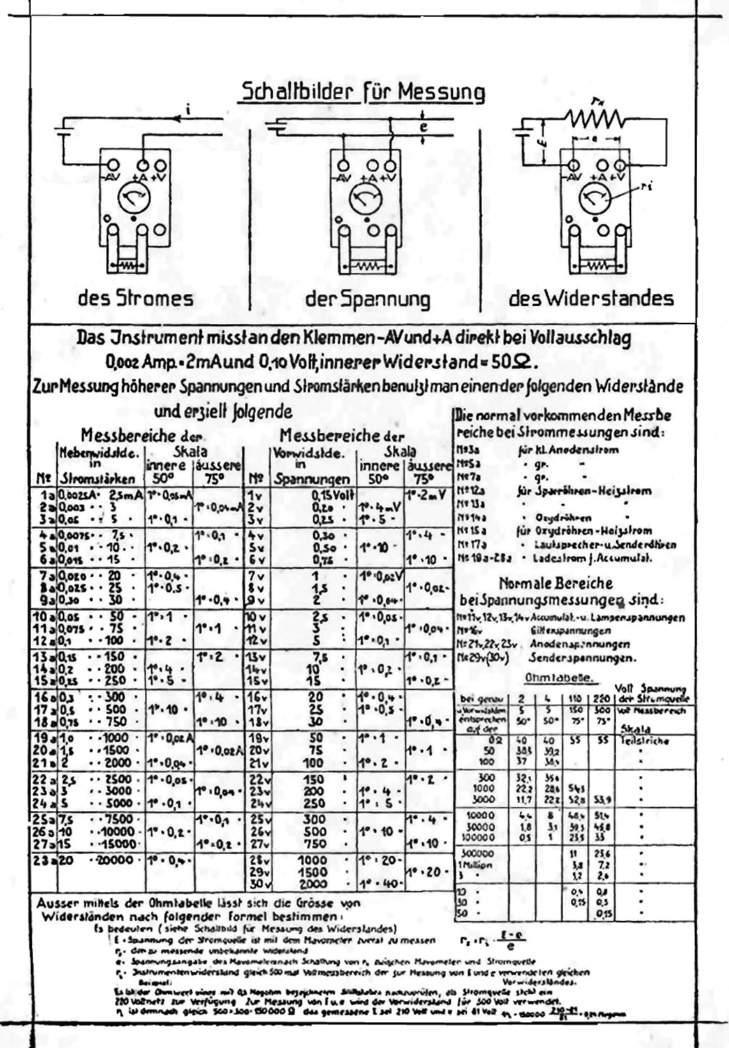
Mavometer Original Gossen D.R.P. . Terza parte.
Inventario D del 1933/1937 al n° 509 si legge: “Mavometer m. e. – Original Gosssen 2 mA fondo scala. Quantità 7. ₤ 700. Prima destinazione, (Lab. Radio)”.
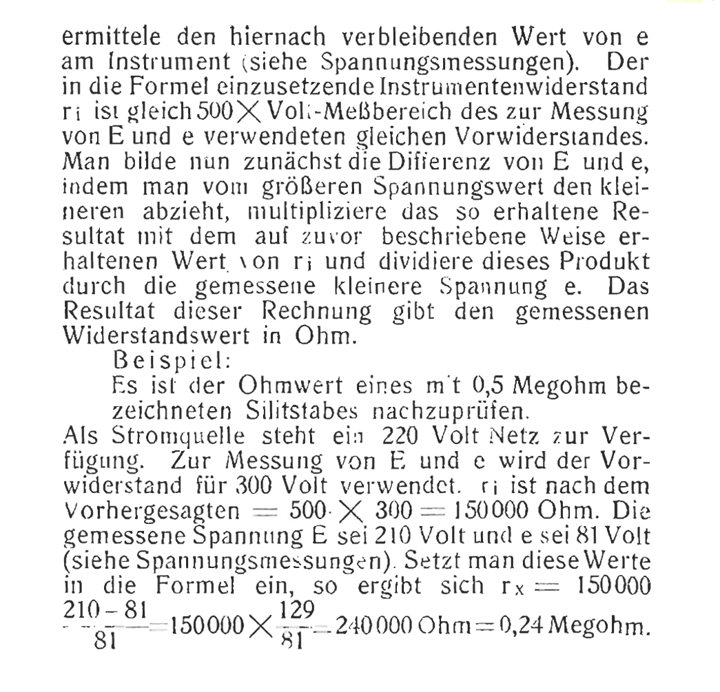
Abbiamo ritenuto opportuno riportare le pagine delle istruzioni sul Mavometer e sui Maweco che si trovano all’indirizzo:
https://www.historische-messtechnik.de/downloads/gossen_radio-universal-mavometer_handbuch.pdf
Per consultare la le altre schede scrivere: “Gossen” su Cerca.
Foto di Claudio Profumieri, elaborazioni e ricerche di Fabio Panfili.
Per ingrandire le immagini cliccare su di esse col tasto destro del mouse e scegliere tra le opzioni.



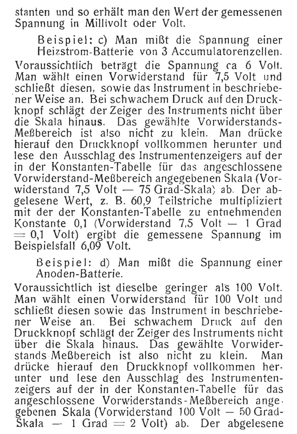


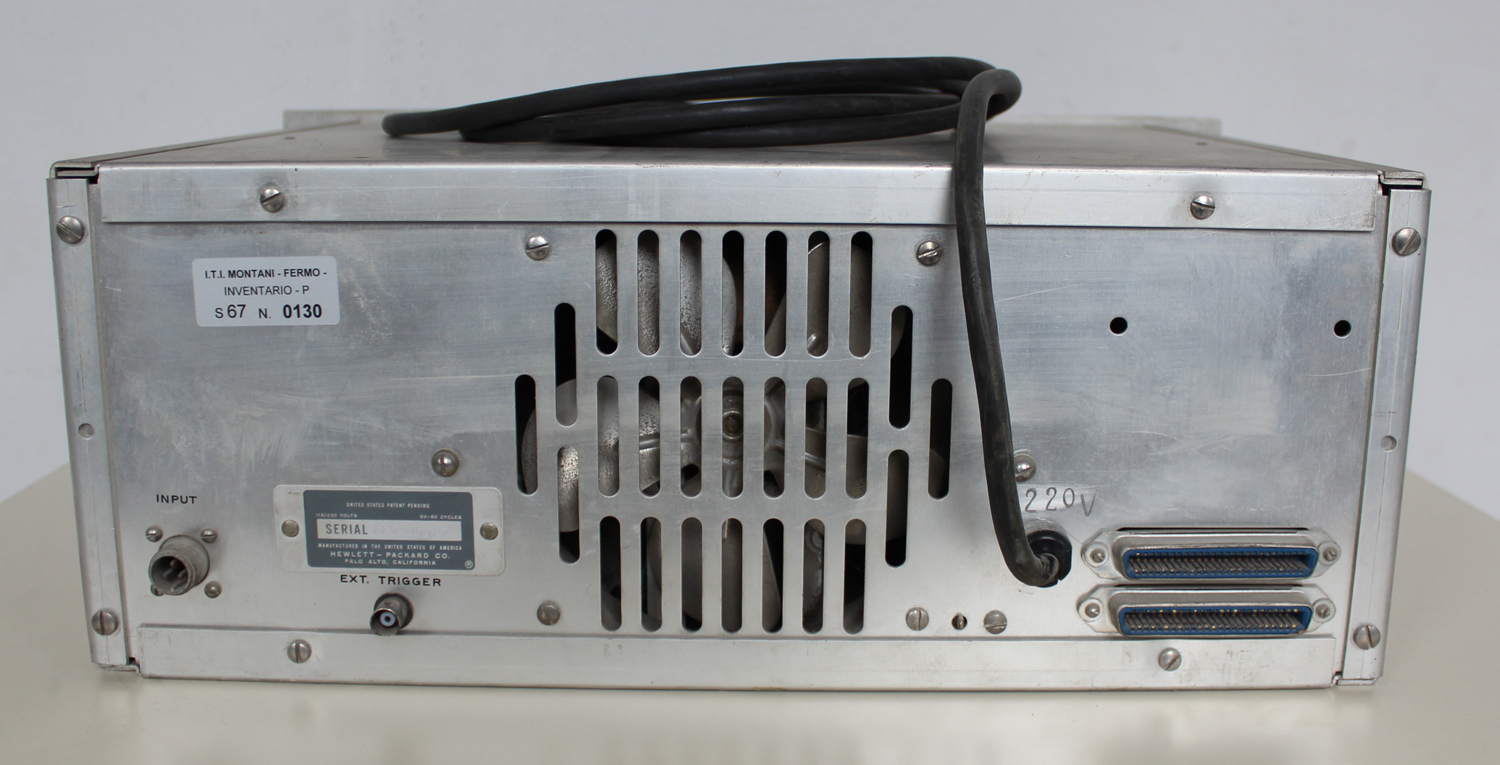
Automatic DC Digital Voltmeter HP 405 AR Hewlett Packard Serial 129-00327 2ª parte.
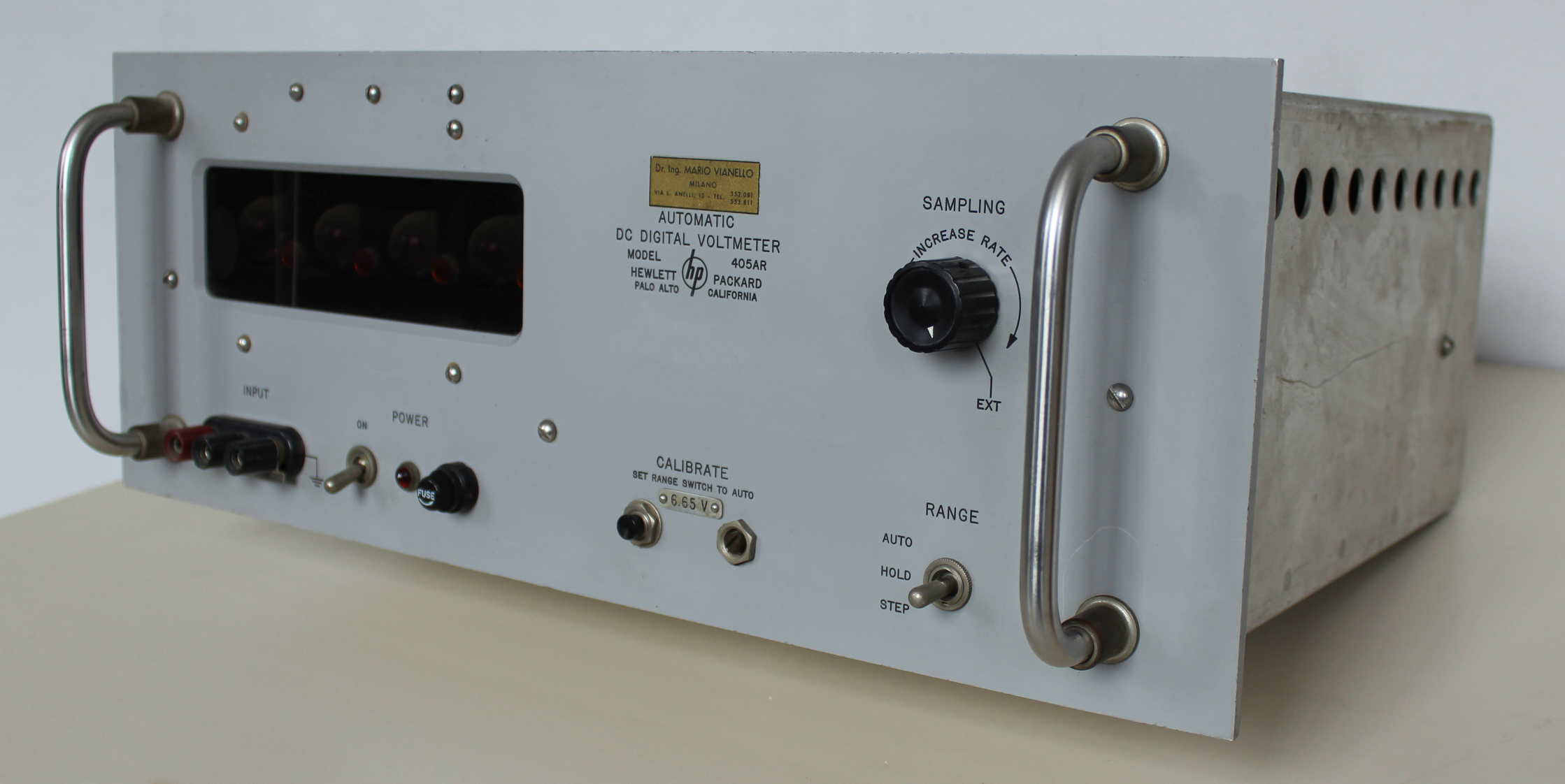
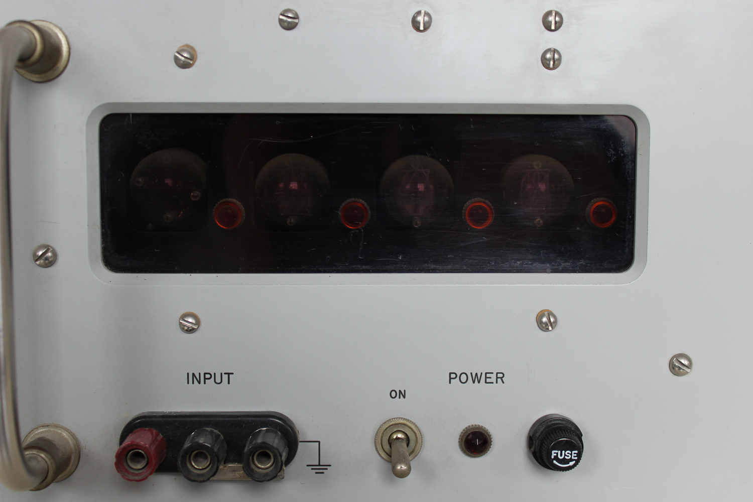 Automatic DC Digital Voltmeter HP 405 AR, della Hewlett Packard Palo Alto California. Serial 129-00327. Seconda parte
Nell’inventario D del 1956, in data 7 giugno 1960, al n° 1801 si legge: “Fondazione Carlo e Giuseppe Piaggio. Voltmetro elettronico hp mod. 405AR. Destin. RAD.”.
Importatore Dr. Ing. Mario Vianello – Milano.
In internet è facile trovare molte informazioni al riguardo ad esempio agli indirizzi:
http://www.hpl.hp.com/hpjournal/pdfs/IssuePDFs/1959-01.pdf
http://hpmemoryproject.org/wa_pages/wall_a_page_02.htm
http://www.hparchive.com/Catalogs/HP-Catalog-1960-Short-Revised.pdf
http://hparchive.com/Catalogs/HP-Catalog-1963.pdf
Riportiamo qui di seguito alcune parti del manuale di istruzioni conservato presso il “Museo ombra”.
Il testo prosegue dalla prima parte.
§§§
«2-5 OPERATION WITH DIGITAL RECORDERS
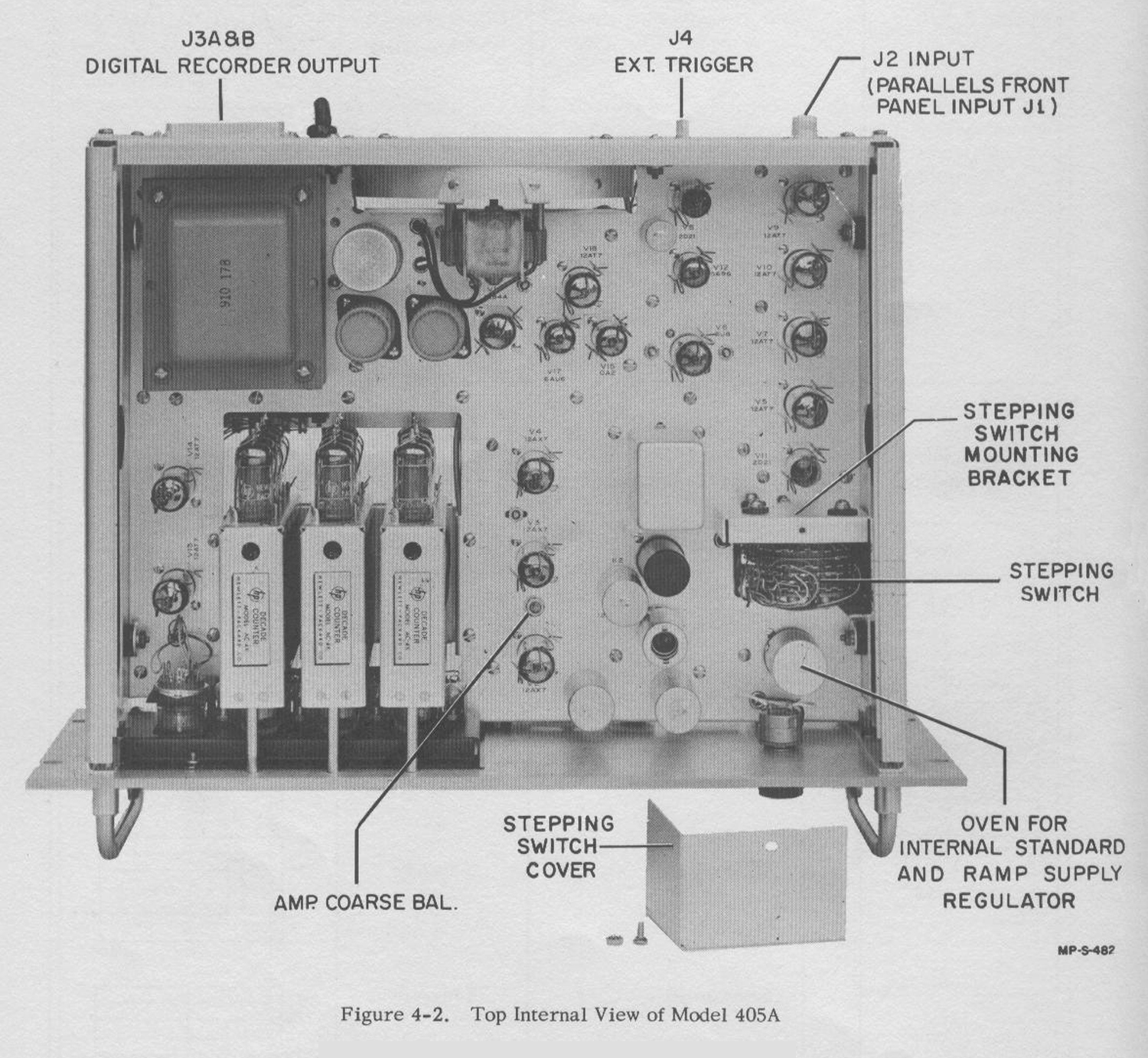
With –hp- Model 560A or 561B Digital Recorder you can obtain permanent printed records of 405A measurements. An example of printed records is shown below. The 3rd, 4th and 5th columns from the right show the digits that appear on the 405A. The 2nd column from the right indicates polarity, blank for positive and (-) for negative. The right-hand column indicates decimal location from the right. The 405A can drive the 561B directly; the standard 561B cable makes the necessary connections between the voltmeter and recorder. However, the 405A-95C Digital Recorder Adapter is required to connect the 405A to the 560A. The adapter mates with the 100-pin output connector on the rear of the 405A and is held in place by two machine screws. The standard 560A cable connects to the adapter. When connecting either recorder to the 405A, be sure both the recorder and 405A are turned off.
CAUTION
The 405A chassis is connected to power-line ground through the adapter/560A system. Do not connect the voltmeter common lead roan off-ground potential while the 560A is connected to the volt-meter.
————
2-6 ELECTRICAL OUTPUT INFORMATION
You can use the electrical information provided by the 405A for other purposes than operating a recorder. For example, you might use the information to operate a remote readout identical to the one in the instrument or to record voltage information on punched cards or tape. Table 2-1 gives full details of the information available and the counters display the total number of pulseswhich passed through the gate.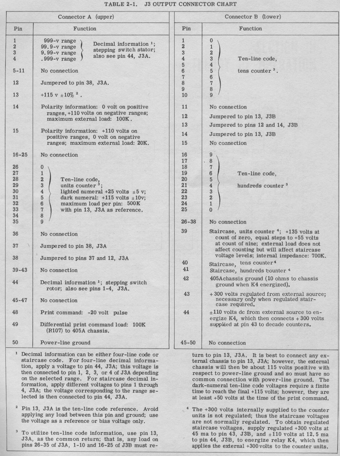 The Ramp Gate Multivibrator returns to its stable condition, closing the Ramp Gate, about 30 milliseconds after it starts the ramp; and should there be no output from the amplifier, the Oscillator Gate Multivibrator returns to its stable condition at about the same time. Thus the instrument can count to about 1-1/2 times full scale.
OMISSIS
Nel processo di scanner abbiamo inavvertitamente saltato la pagina 3.1 e, nel redigere il testo, ci troviamo per ora nell’impossibilità di accedere al manuale di istruzioni per la chiusura del Montani causa Covid 19 (o SARS-COV2). Ce ne scusiamo con i visitatori.
 3-4 ZERO-SETTING THE VOLTMETER
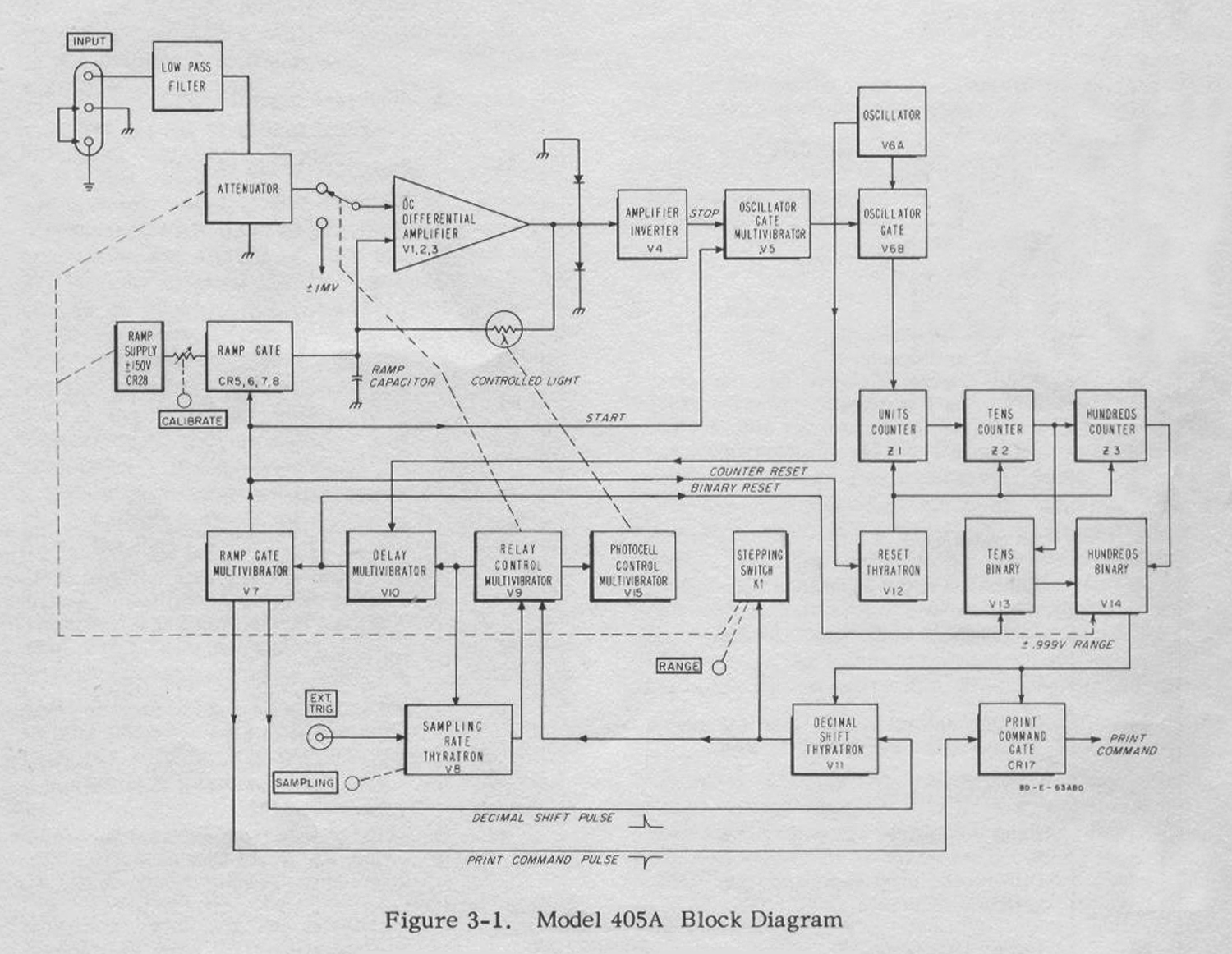
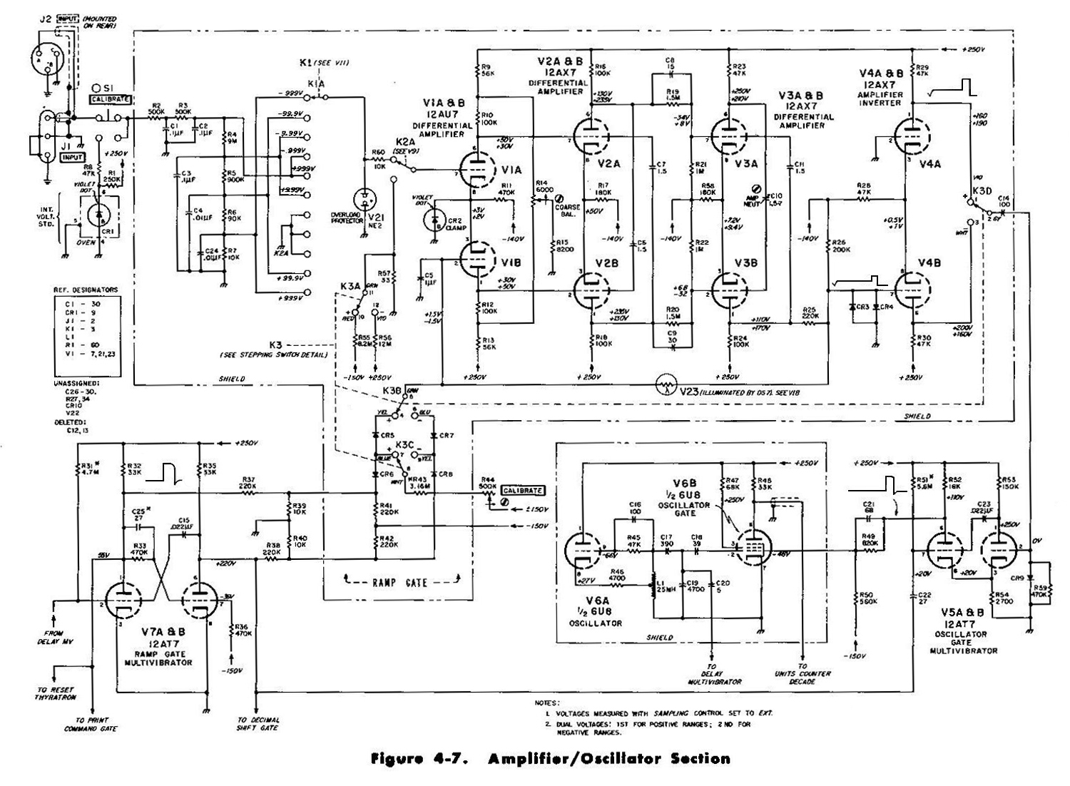
To insure that the ramp always starts from the correct voltage, the ramp is zero-set prior to each measurement. Two multivibrators, Relay Control Multivibrator V9 and Photocell Control Multivibrator V15, zero-set the ramp. The Relay Control Multivibrator energizes a relay which applies il mv to the input grid of the amplifier. The polarity of this voltage is opposite to the polarity of the displayed range and assures a readout of .000 when the instrument measures .000 volt. The Photocell Control Multivibrator illuminates a photocell in a feedback loop around the amplifier. When the photocell is illuminated its resistance drops to a low value, and it applies total negative dc feedback to the amplifier. Thus any voltage at the amplifier output is totally fed back and essentially cancelled. Cancellation is not complete because of the internal unbalance and drift of the amplifier and the ± 1 mv applied to the amplifier input grid. However, amplifier output and ramp grid input come to less than ± 100 mv.
The ramp is zero-set at this time, for the ramp capacitor is connected to the ramp grid of the amplifier and so charges to the feedback voltage. The ramp capacitor maintains this voltage on the ramp grid between the time the Photocell Control Multivibrator opens the feedback loop and the start of the ramp, and amplifier drift is not fast enough to upset the balance in the time of a single measurement. Thus the ramp always starts from the zero-set value.
Amplifier gain jumps from unity to over 1000 when the feedback loop is opened. Amplifier output (less-than ± 100 mv) then becomes less than ± 100 µvolt when referred to the input. Therefore the voltmeter is zero-set to within 100 µvolt of zero.
The Photocell Control Multivibrator opens the feedback loop (by turning off the light shining on the photocell) before the Relay Control Multivibrator de-energizes the relay. Thus the attenuated input voltage is applied to the amplifier after the feedback loop opens and cannot upset ramp zero.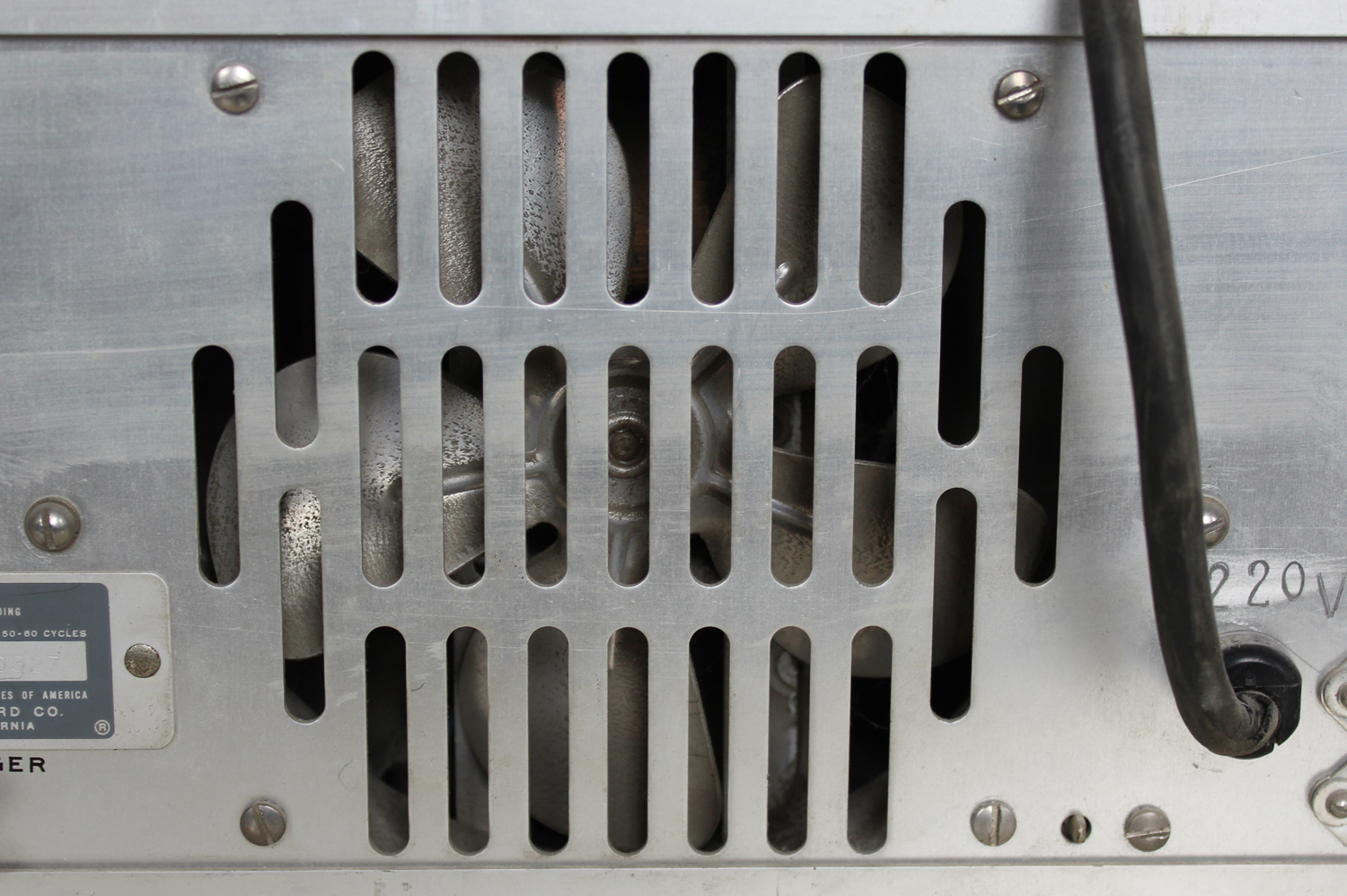 3-5 THE MEASUREMENT PROCESS
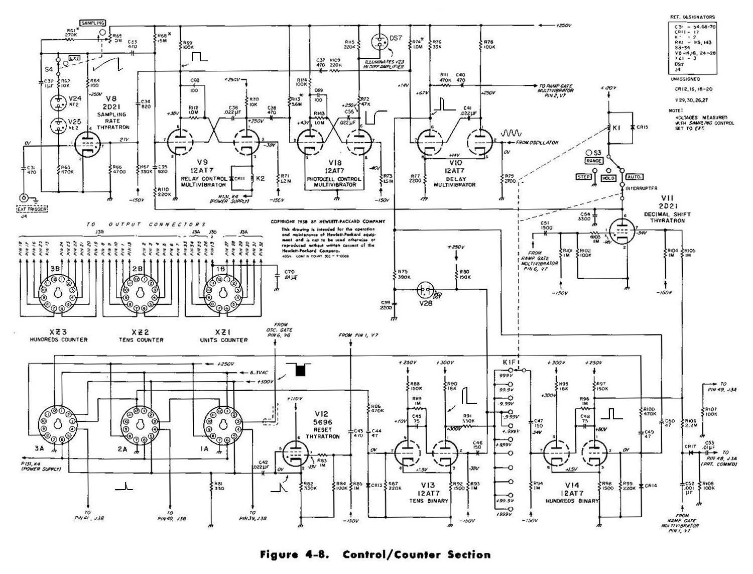
Sampling Rate Thyratron V8 starts the measurement process by triggering the Relay Control Multivibrator, V9. The Relay Control Multivibrator immediately triggers Photocell Control Multivibrator V15, and these two multivibrators zero-set the ramp. After about 80 msec, the Photocell Control Multivibrator returns to its stable condition, darkening the photocell. Some 30 msec later the Relay Control Multivibrator returns to its stable condition, de-energizing the relay and triggering Delay Multivibrator V10. The Delay Multivibrator allows the relay to completely dc-energize before the start of the ramp. The delay is about 4 msec.
When the Delay Multivibrator returns to its stable condition, it triggers the Ramp Gate Multivibrator, V7, to start the ramp and open the Oscillator Gate, V6B. Oscillator V6A synchronizes the return of the Delay Multivibrator to its stable condition. Thus there is no count ambiguity at the start of the ramp.
When the ramp voltage equals the attenuated input voltage, the DC Differential Amplifier closes the Oscillator Gate, and the readout indicates the voltage applied to the instrument.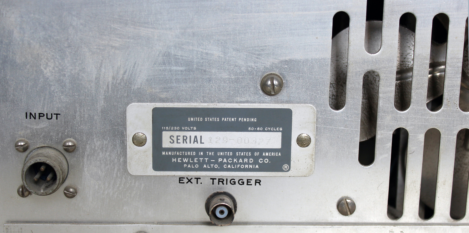 3-6 CHECKING RANGE
During each measurement the 405A checks the range by monitoring the output of the Tens and Hundreds Counters. If there is no output from the Tens Counter, the range is too high, for the ramp voltage equals the attenuated input voltage before the counters register 100 counts. If the Hundreds Counter produces an output, the range is too low or of the wrong polarity, for the counters count off scale before the ramp voltage equals the attenuated input voltage. Thus the range is correct only when the Tens Counter produces at least one output pulse, but the Hundreds Counter produces none.
Tens Binary V13 and Hundreds Binary V14 do the monitoring. The Tens Binary is reset by Delay Multivibrator V10 when that multivibrator triggers the Ramp Gate Multivibrator. The Tens Binary in turn resets the Hundreds Binary. (Binaries have two stable conditions. Hereafter, condition 0 is the reset condition; condition 1, the non-reset condition.) With no output from the Tens Counter, both binaries remain in condition 0. The first output pulse from the Tens Counter switches the Tens Binary to condition 1, and the Tens Binary immediately switches the Hundreds Binary to condition 1 also. Succeeding pulses from the Hundreds Counter switches the Hundreds Binary back to condition 0. Succeeding pulses have no effect. Therefore, if the measurement ends with the Hundreds Binary in condition 1, the range is correct; if the measurement ends with the Hundreds Binary in condition 0, the range is wrong.
There is a direct reset line from the Delay Multivibrator to the Hundreds Binary (not shown in Figure 3-1); so the Delay Multivibrator directly resets the Hundreds Binary in the event the Tens Binary is in condition O and the Hundreds Binary in condition 1. However, this combination seldom occurs. To prevent continual ‘recycling when the 405A measures voltages from + 0.099 to -0.099 volt, the Hundreds Binary is reset to condition 1 on the +999 and -.999 volt ranges. Thus the instrument shifts from these ranges only after off-scale counts.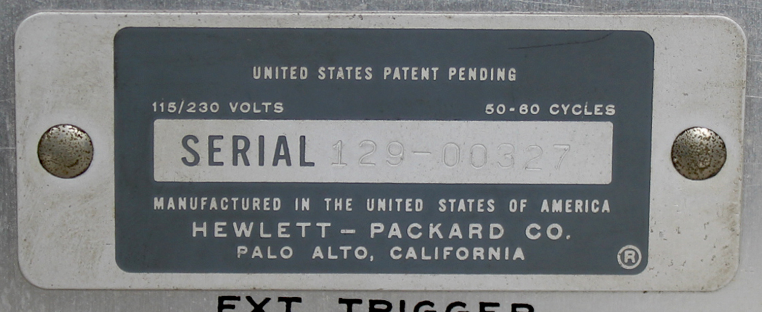 3-7 DECIMAL SHIFT CONTROL
The Hundreds Binary determines whether or not the 405A shifts range by controlling Decimal Shift Thyratron V11 and Print Command Gate CR17. When in condition 1 (correct range), the Hundreds Binary holds the Decimal Shift Thyratron off and opens the Print Command Gate. When in condition 0 (wrong range), the Hundreds Binary lets the Decimal Shift Thyratron fire if triggered and closes the Print Command Gate.
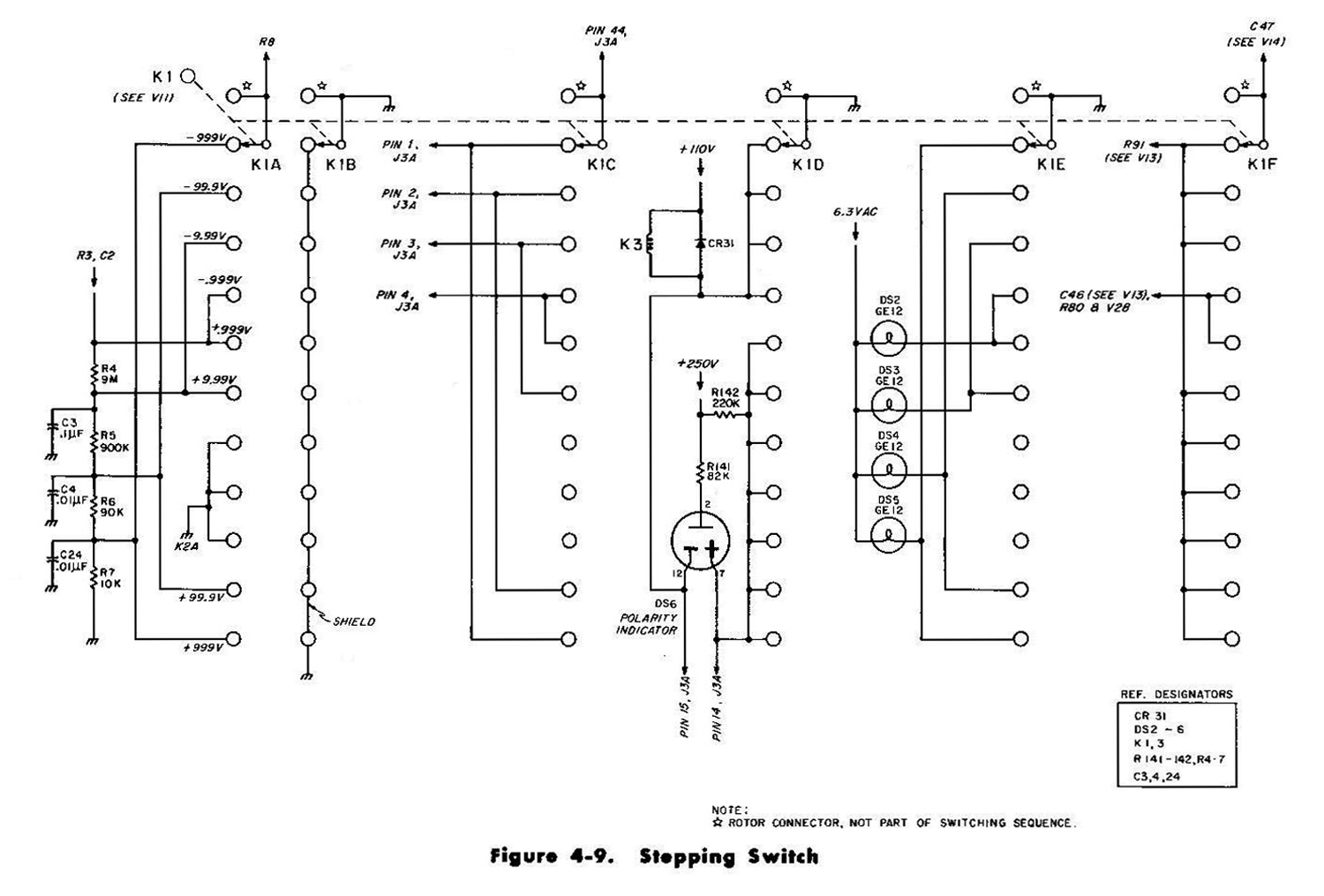
When the Ramp Gate Multivibrator returns to its stable condition and closes the Ramp Gate, it applies a positive pulse to the Decimal Shift Thyratron and a negative pulse to the Print Command Gate. If the range is correct, the negative pulse passes through the Print Command Gate to, be used as a trigger for a remote recorder. The Decimal Shift Thyratron is held off. If the range is wrong, the Print Command Gate is closed, but the positive pulse fires the Decimal Shift Thyratron. The Decimal Shift Thyratron then shifts the instrument to the next more positive range (by moving Stepping Switch K1 one step) and triggers Relay Control Multivibrator V9 to start another measurement.
When triggered, the Relay Control Multivibrator triggers Sampling Rate Thyratron V8. The Sampling Rate Thyratron then cannot fire during a measurement started by the Decimal Shift Thyratron.
To prevent continual recycling when the 405A measures voltages from + 0.099 to -0.099 volt, the Hundreds Binary is reset to condition 1 on the +.999 and -.999 volt ranges. Thus the instrument shifts from these ranges only after off-scale counts».
§§§
OMISSIS MAINTENANCE
Per consultare la prima parte scrivere “405AR” su cerca.
Foto di Claudio Profumieri, elaborazioni e ricerche di Fabio Panfili.
Per ingrandire le immagini cliccare su di esse col tasto destro del mouse e scegliere tra le opzioni.
Automatic DC Digital Voltmeter HP 405 AR Hewlett Packard Serial 129-00327 1ª parte
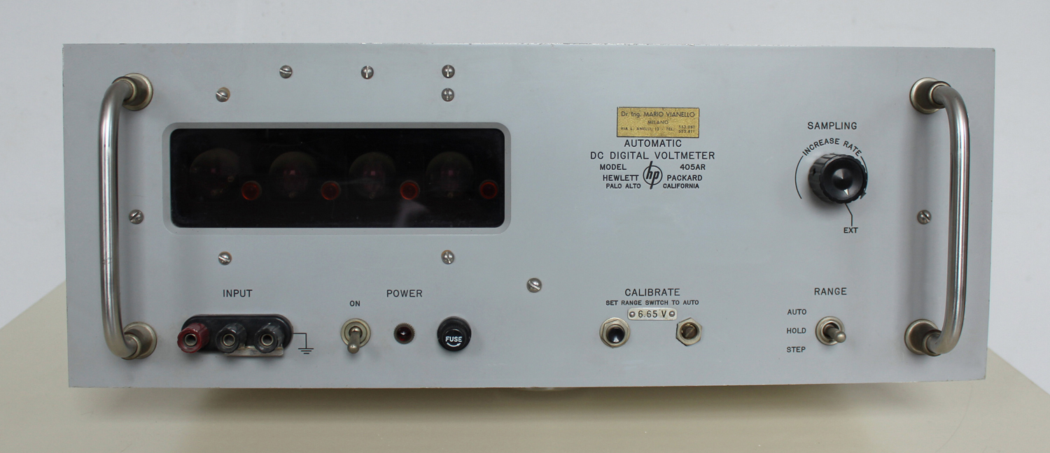
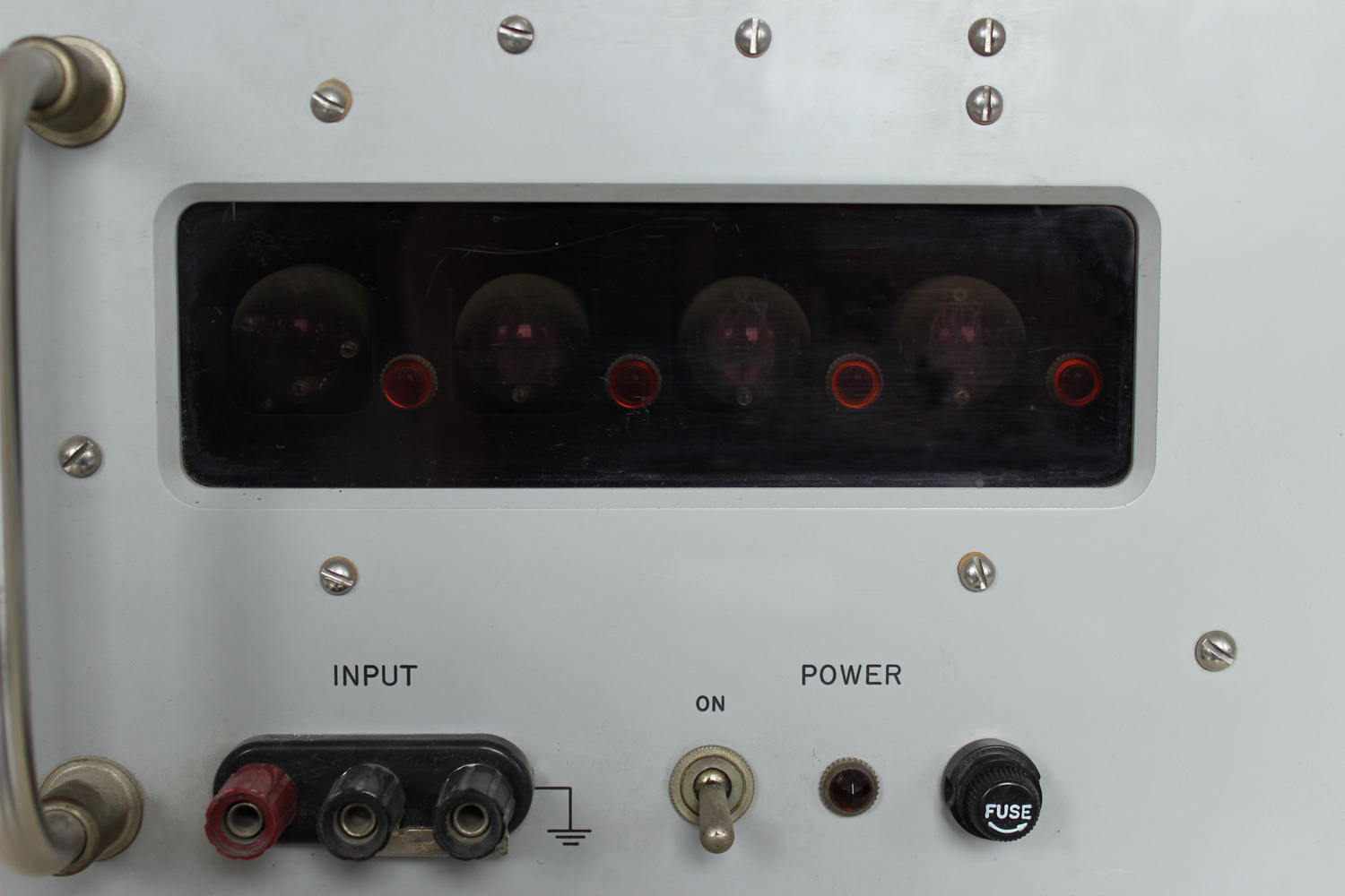
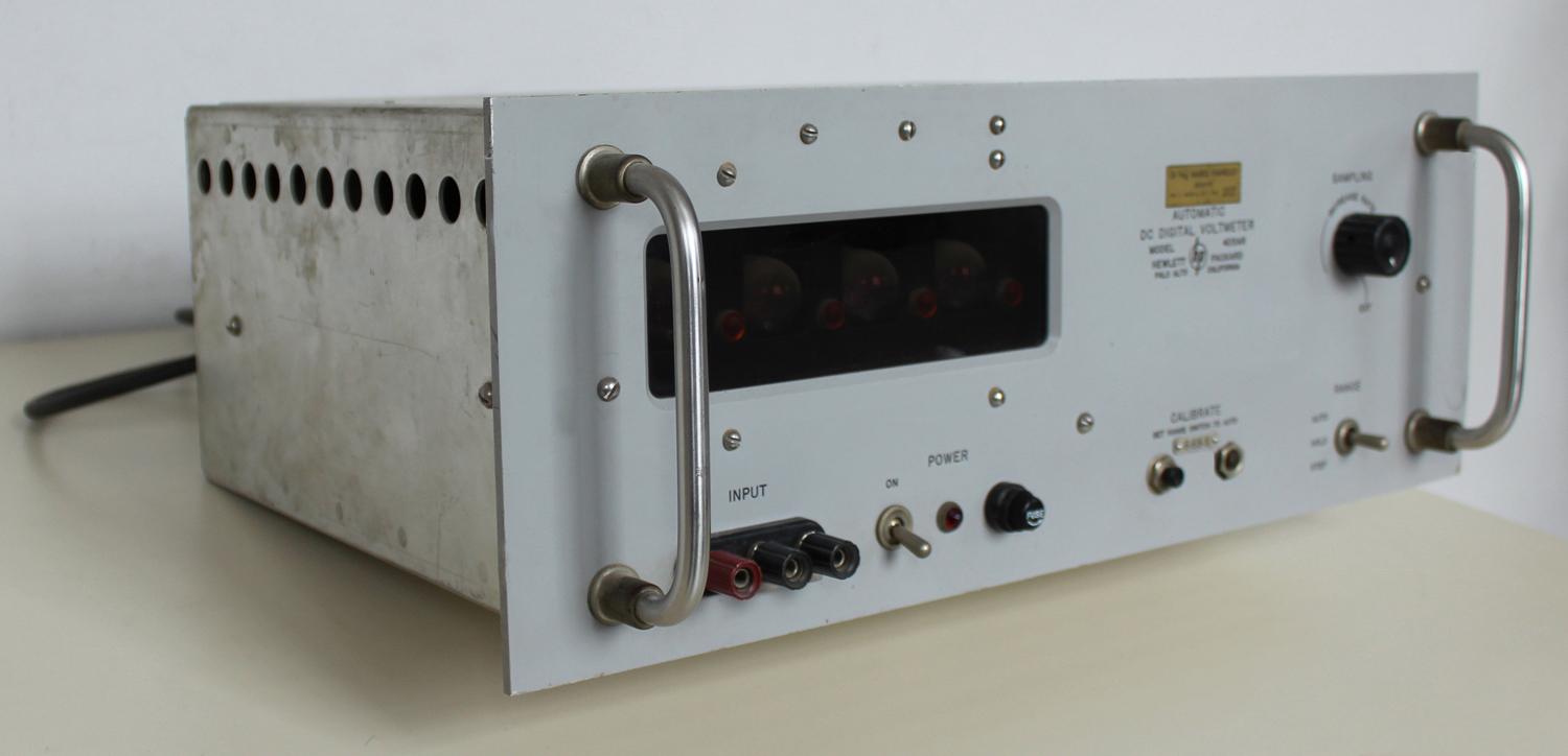 Automatic DC Digital Voltmeter HP 405 AR, della Hewlett Packard Palo Alto California. Serial 129-00327. Prima parte.
Nell’inventario D del 1956, in data 7 giugno 1960, al n° 1801 si legge: “Fondazione Carlo e Giuseppe Piaggio. Voltmetro elettronico hp mod. 405AR. Destin. RAD.”.
Importatore Dr. Ing. Mario Vianello – Milano.
In internet è facile trovare molte informazioni al riguardo ad esempio agli indirizzi:
http://www.hpl.hp.com/hpjournal/pdfs/IssuePDFs/1959-01.pdf
http://hpmemoryproject.org/wa_pages/wall_a_page_02.htm
http://www.hparchive.com/Catalogs/HP-Catalog-1960-Short-Revised.pdf
http://hparchive.com/Catalogs/HP-Catalog-1963.pdf
Riportiamo qui di seguito alcune parti del manuale di istruzioni conservato presso il “Museo ombra”.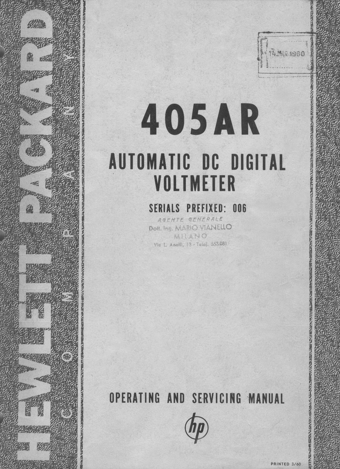
§§§
«SECTION I
GENERAL DESCRIPTION
1-1 IDENTIFICATION
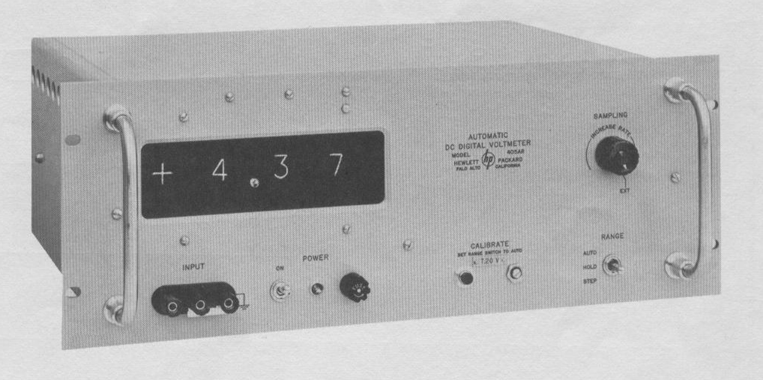
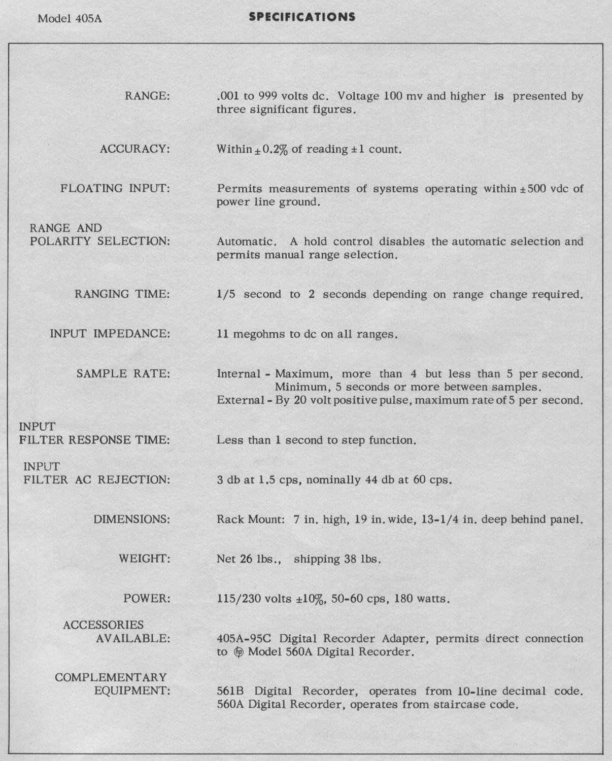
The -hp- Model 405A Automatic DC Digital Voltmeter measures positive or negative voltages from 1 millivolt to 999 volts. It can select range and polarity automatically to display voltages from 100 millivolts to 999 volts to three significant figures.
1-2 COOLING
The 405A uses forced-air cooling to maintain tolerable temperatures within the cabinet. Exhaust fan and air outlet are located on the instrument rear; air intakes, on the sides. Allow at least 2 in. clearance about instrument sides and rear for proper ventilation.
1-3 STEPPING SWITCH
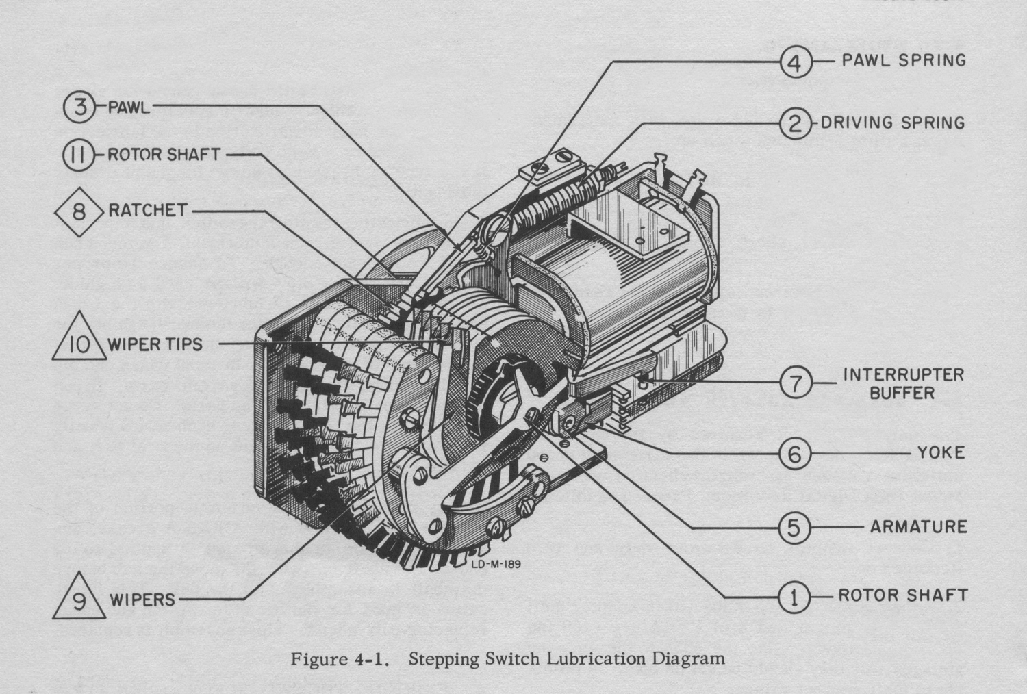
The 405A uses a relay-operated stepping switch for ranging. Although the switch requires infrequent service, it is important to service it when due. See Section IV, Maintenance.
1-4 POWER LINE VOLTAGE
The 405A is normally wired for use from a 115-volt, 50-60 cps power source. To convert it for use from a 230-volt power source, change the
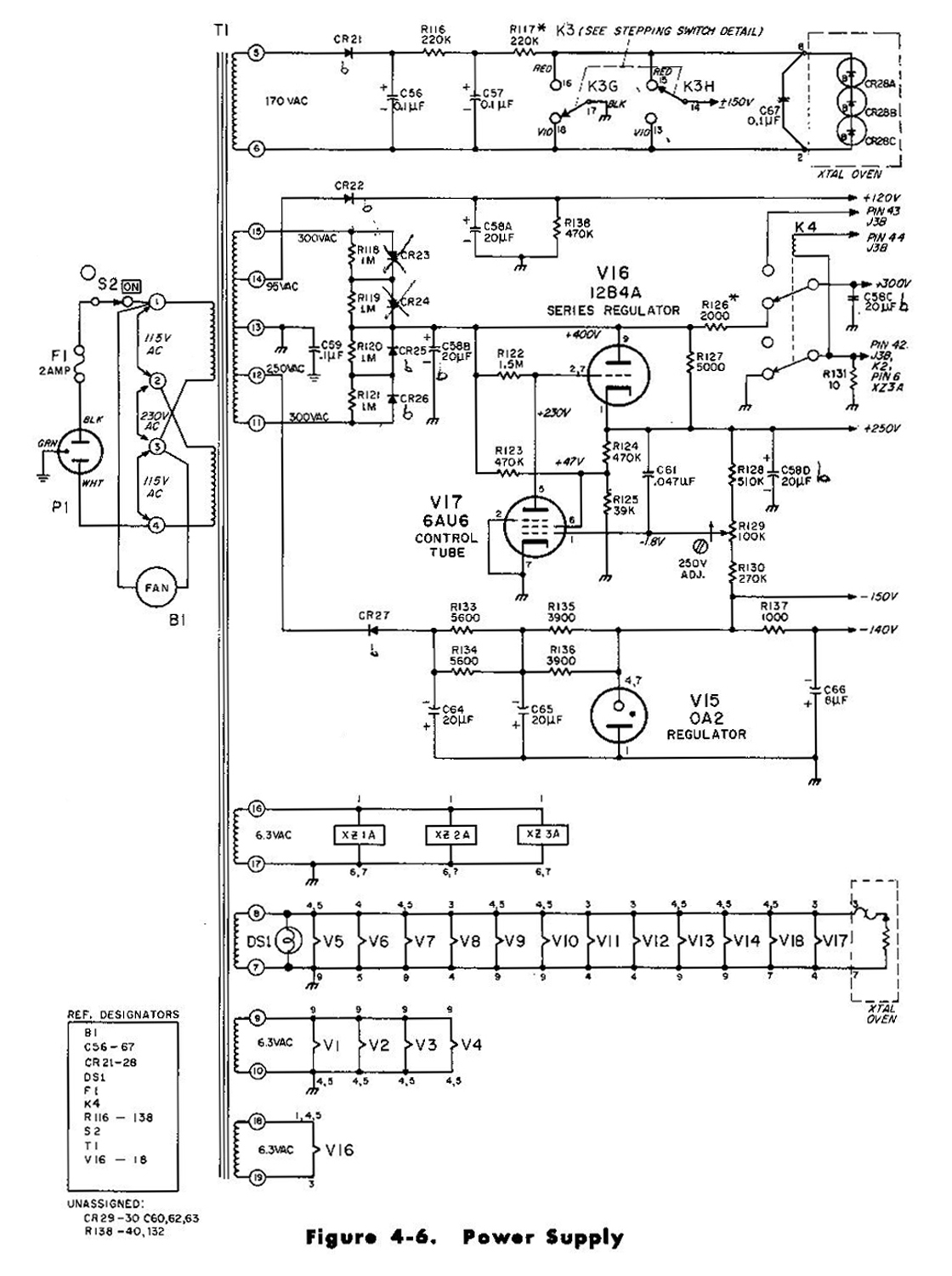
dual 115-volt primary windings of the power transformer from a parallel combination to a series combination. See the schematic diagram for details. At the time of conversion, change the line fuse from a 2-ampere, slow-blow type to a 1-ampere, slow-blow type.
1-5 THREE CONDUCTOR POWER CABLE
This instrument is equipped with a three conductor power cable terminated with a polarized connector recommended by the National Electrical Manufacturers’ Association (NEMA). The third green conductor is terminated in a round pin added to a standard two-blade connector. With the NEMA connector plugged into an appropriate receptacle, the third lead grounds the instrument cabinet for the protection of operating personnel. To use the NEMA connector in a two-contact receptacle, you should use a three-prong to two-prong adapter. The ground lead emerges from the adapter as a short green lead which should be connected to a grounded receptacle box.
1-6 DAMAGE IN SHIPMENT
Inspect and operate this instrument upon receipt. Section IV, Maintenance, contains a performance check which is a good test as part of incoming quality control inspection. If there is any damage, see the “Claim for Damage in Shipment“ sheet in this manual.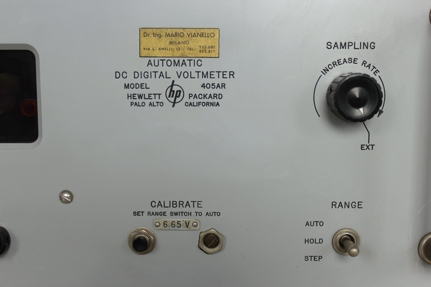
 SECTION II
OPERATING INSTRUCTIONS
2-1 AUTOMATIC OPERATION
1) Turn instrument ON. Instrument can be used within 1 minute of turn on, but requires 15 minutes warm up before calibration against internal standard brings it within specified accuracy. See paragraph 2-3.
2) Set SAMPLING control to desired sampling rate.
To control sampling rate externally, set SAMPLING control to EXT and connect triggering signal to EXT TRIGGER connector on instrument rear.
Trigger must be a positive step at least 20 volts peak and have repetition rate no greater than 5 per second.
NOTE
The instrument requires about 1 second to fully respond to sudden input-voltage changes (see paragraph 2-4); therefore delay the external trigger about 1 second after any sudden change in applied voltage.
———–
3) Connect voltage to he measured to INPUT connector and read its value. A parallel INPUT connector is located on instrument rear.
CAUTION
When measuring voltage between two points which are both off ground potential, remove the shorting strap between power-line ground and chassis-ground terminals of front-panel INPUT connector.
————
2-2 MANUAL OPERATION
Manual operation permits manual selection of range and is intended for measuring voltages which produce readings of 999 or 100 regardless of decimal position. In either case, a varying input voltage might cause the instrument to continuously change ranges if it is operating automatically. Manual operation permits measurement of some voltages to four figures, for the instrument can measure to about 150% of full scale. By holding the instrument on the range just below the correct range, you obtain the second, third, and fourth figures from the readout; the first figure, which is lost, is always 1. However, instrument accuracy deteriorates above full scale. Manual operation is convenient for measuring a series of voltages quite close in value, for the instrument will not cycle through its ranges as you move the probe from one test point to another.
1) Set RANGE switch to HOLD. Instrument will remain on its displayed range.
2) To change ranges, set RANGE switch to STEP. This is a spring-loaded position, and switch returns to HOLD when released. Instrument steps to next more positive range each time you release RANGE switch from STEP except that three blank positions occur between +9.99 and +99.9 volt ranges. The decimal point is not lighted on the blank ranges.
2-3 CALIBRATION
The 405A has an internal secondary voltage standard to check its calibration. The push-button CALIBRATE switch, located on the front panel, applies this voltage to the instrument and disconnects the INPUT connector. Calibrate the instrument, after sufficient warm up, each time you turn it on. Once set, calibration need seldom be checked. Proceed as follows:
1) Turn instrument ON and allow 15-minute warm up.
2) Set SAMPLING control to maximum sampling rate (full clockwise but not to EXT).
3) Set RANGE switch to AUTO.
4) Note voltage indicated below CALIBRATE engraving on front panel. This is the internal secondary standard voltage.
5) Press CALIBRATE switch and adjust CALIBRATE control until readout agrees with internal secondary standard voltage.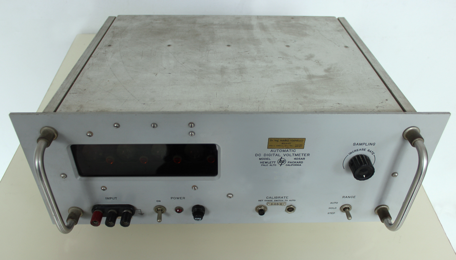 2-4 INPUT FILTER
The 405A measures instantaneous dc voltages. To avoid readout variations due to superimposed ac signals, the instrument has a low-pass RC filter at its input. The filter has a sharp cutoff and attenuates 60-cps signals about 50 db. Thus a 60-cps signal with a peak value equal to full scale of the displayed range typically causes a readout variation of ± 4 counts. Since the filter is at the input, it becomes charged to the full value of the input voltage. With the input open-circuited (probe lifted off test point), the filter capacitors must discharge through the input attenuator, and after 2 seconds they still have about 37% of their original charge. (You can see the discharge by watching the readout decrease after the probe is removed from a voltage source.) Therefore, if you quickly change the probe from a high- voltage point to a low-voltage point, you will apply nearly the full high voltage stored in the filter capacitors to the low-voltage point through 500K resistance. If the low-voltage point happens to be a high-impedance point such as a vacuum tube grid or, possibly, a transitor element, the voltage applied through the probe may upset circuit operation to the point that the circuit will damage itself.
A GOOD OPERATING PRACTICE IS TO TOUCH THE PROBE TO GROUND BRIEFLY OR ALLOW THE FILTER SUFFICIENT TIME TO DISCHARGE WHEN CHANGING THE PROBE FROM HIGH- VOLTAGE POINTS TO LOW-VOLTAGE POINTS.
In any case be sure the readout is less than the expected voltage before connecting the probe into a low-voltage circuit. The input filter makes instrument response to step functions about 0.75 second compared to about 0.2 second between successive samplings at maximum sampling rate. If you require a response time compatible with maximum sampling rate, remove C1 and replace C2 with two 0.02 μf, 600-vdcw, polystyrene-dielectric capacitors in series.
CAUTION
Since the two capacitors are in series, one will be off ground potential. Be sure to insulate the off-ground capacitor from the chassis.
———
Response time will then be about 50 msec. However, ac rejection will be much less than with the standard filter. For example, a 60-cps signal with a peak value equal to full scale of the displayed range will cause readout variations as much as ± 200 counts».
§§§
Il testo prosegue nella seconda parte. Per consultarla scrivere “405AR” su cerca.
Foto di Claudio Profumieri, elaborazioni e ricerche di Fabio Panfili.
Per ingrandire le immagini cliccare su di esse col tasto destro del mouse e scegliere tra le opzioni.