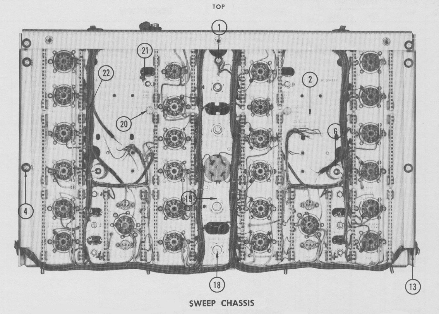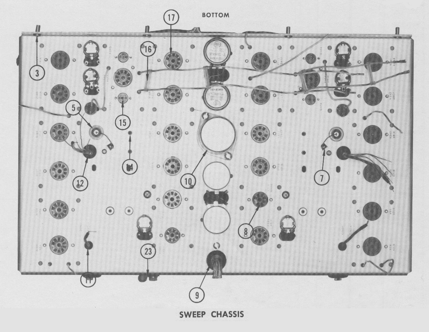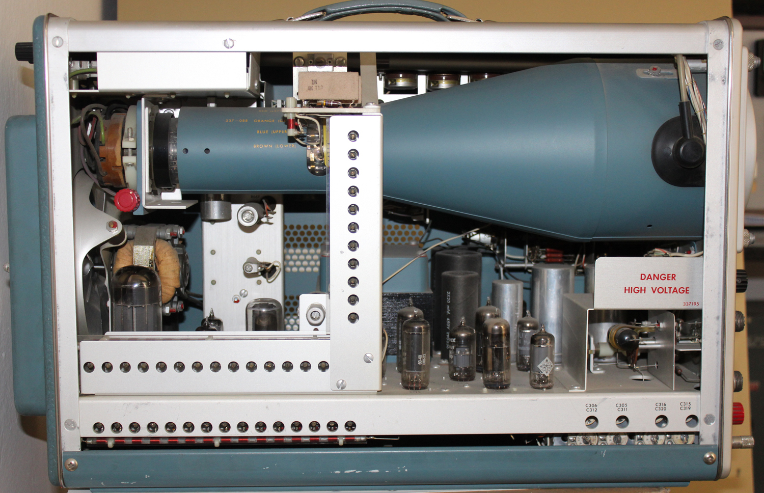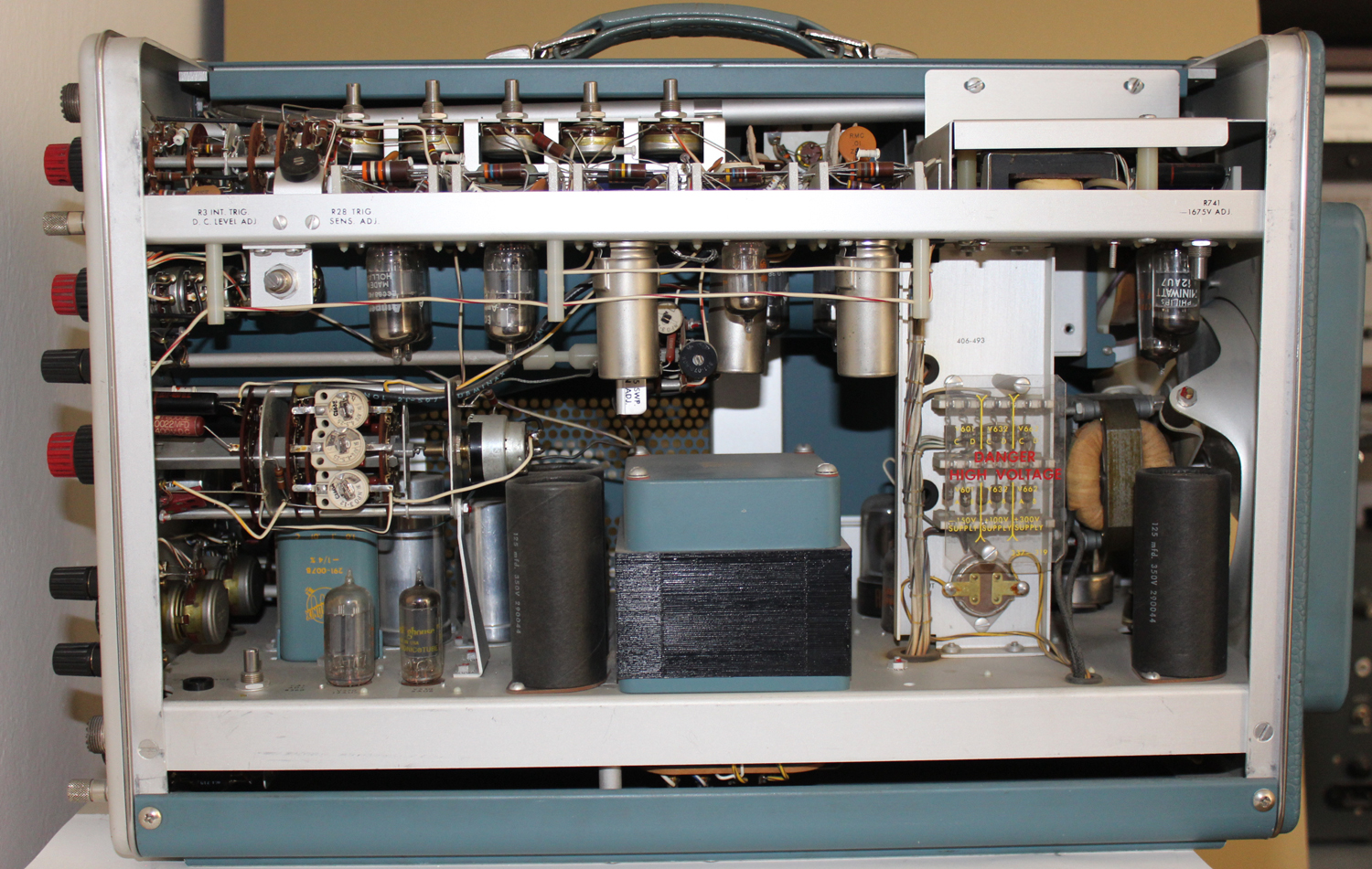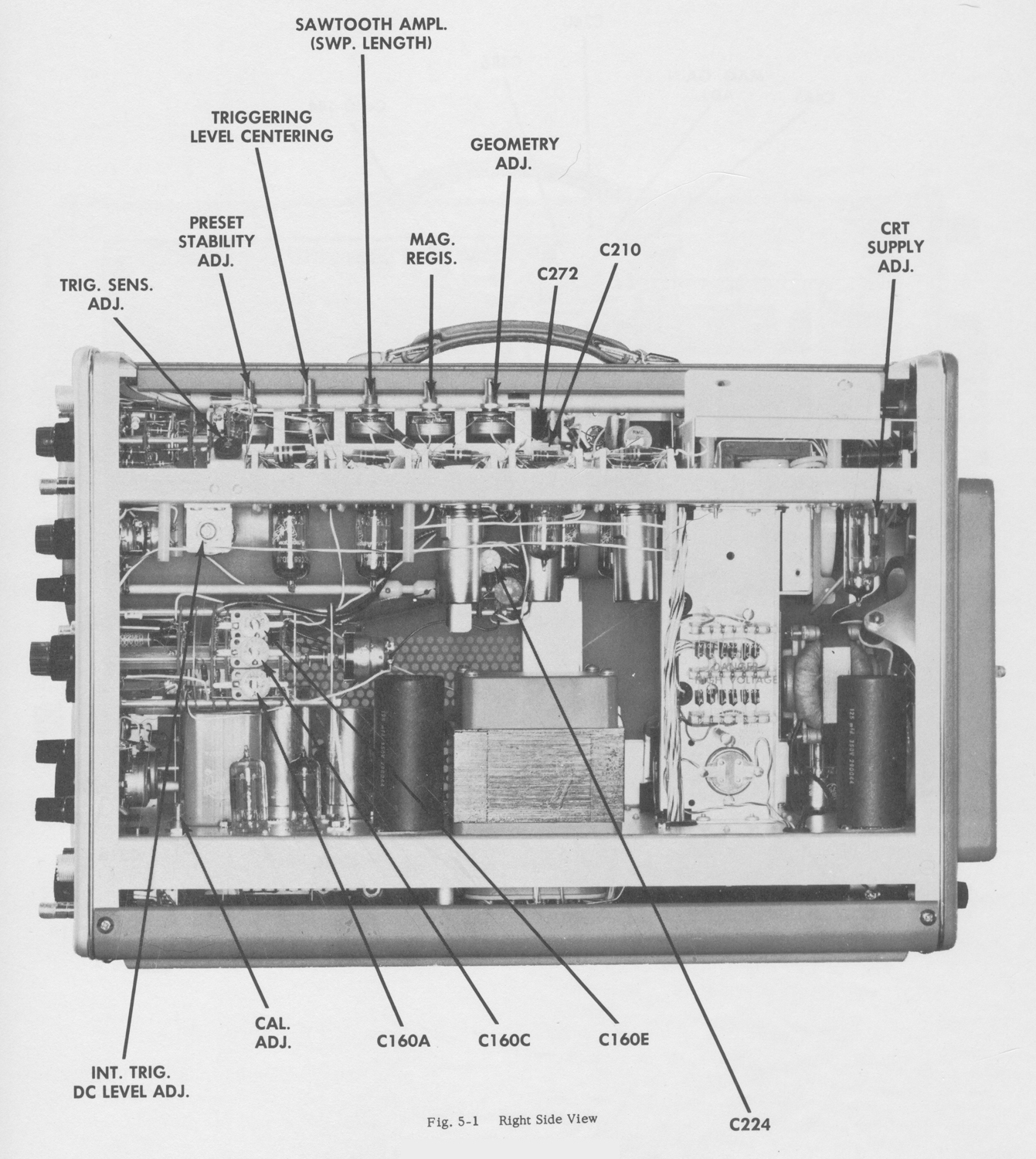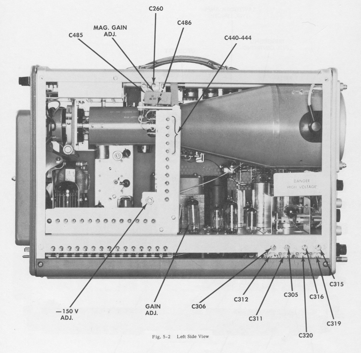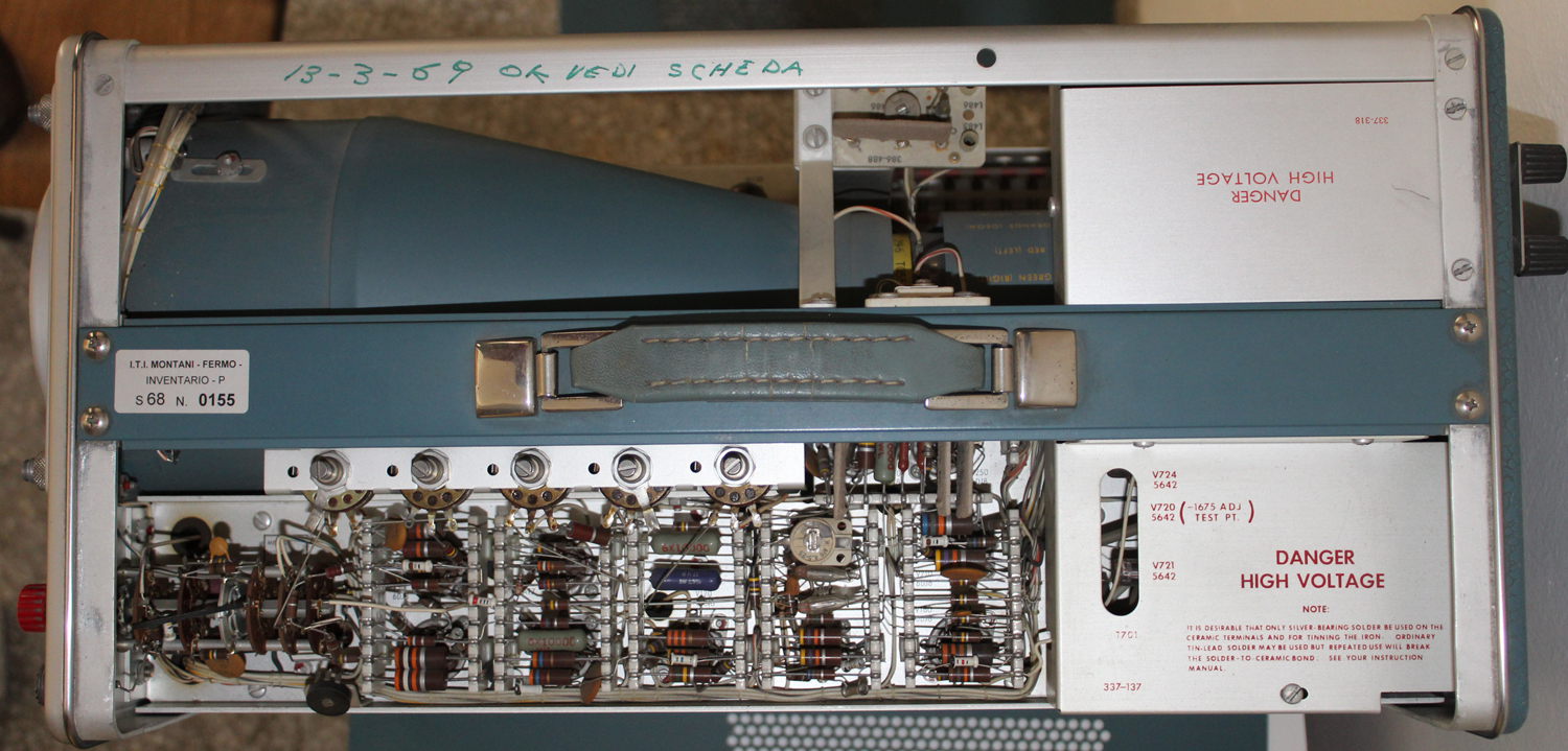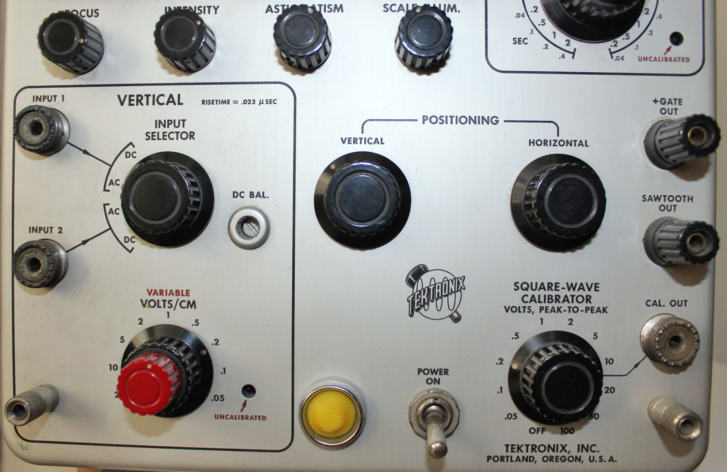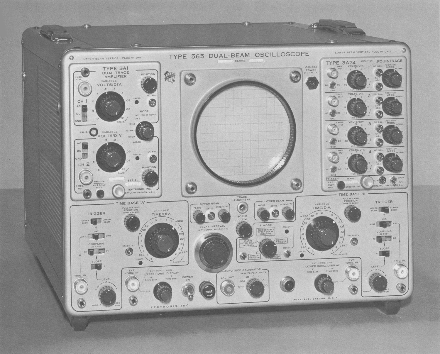
Oscilloscope Tektronix Type 565 serial 689, tirdh part (MITI Museum)

Oscilloscopio Tektronix Type 565, serial 689. Terza parte. 
Nell’inventario D del 1956 si trova al n° 3747 e risulta acquistato nell’agosto del 1964; vi si legge: “Silvestar ltd. Milano. Oscilloscopio Tektronix mod. 565 matr. 689. Dest. Elettronica ₤ 1·678·600”. Insieme alla fotocamera che è al n° 3746, dove si legge: “Silvestar ltd. Milano. Macchina fotografica Tektronix mod. C-12 completa di Bezel-Tektronix. Dest. Elettronica. ₤ 557·700”.
Le prossime schede riportano parte delle istruzioni tratte dal manuale conservato presso la sezione Elettronica del Montani.
§§§
                    «SECTION I                                                                                      CHARACTERISTICS
The Type 565 is a dual-beam oscilloscope; essentially two oscilloscopes in one cabinet. Two internal horizontal and two plug-in vertical deflection systems permit independent operation of the two cathode-ray tube (crt) beams. Either
of the two time-base generators can control the sweep of either or both of the beams.
Each vertical deflection system utilizes any of the Tektronix non-sampling signal amplifier plug-in units intended for use with 560-Series instruments. The choice of plug-in units depends on the application and those used need not be the some type.
Special circuits in the Type 565 Oscilloscope permit an accurate, continuously variable delay in the presentation of
a sweep from 10 microseconds to 50 seconds after receipt of a fast rise triggering impulse. This feature permits expanded observation of a small portion of the normal sweep, accurate measurement of signal jitter, precise time measurement and many other uses.
        VERTICAL DEFLECTION SYSTEM
The characteristics of both vertical channels are those of the plug-in units used. The capacitances of the two vertical deflection plate systems of the cathode-ray tube are equalized to assure uniform plug-in unit high frequency response.
       HORIZONTAL DEFLECTION SYSTEM
Sweep Rates—Time Base ‘A’ and Time Base ‘B’
Calibrated sweep rates of 1 microsecond to 5 seconds per division in 21 steps. An uncalibrated control permits sweep rates to be varied continuously between 1 microsecond and about 12 seconds per division.
Sweep rate accuracy (with 10X MAG. turned off): Upper Beam driven by Time Base ‘A’ and Lower Beam driven by Time Base ‘B’; within 3%.
Both beams driven by Time Base ‘A’; Lower Beam sweep
rate is accurate within 4%.
Both beams driven by Time Base ‘B’; Upper Beam sweep
rate is accurate within 4%,.
Simultaneous crossed operation not recommended (Upper Beam driven by Time Base ‘B’ and Lower Beam driven by Time Base ‘A’).
10X Magnifier—Upper and Lower Beam
Provides a horizontal magnification of X10 of the center 1-centimeter portion of the unmagnified crt display when the internal time base generators provide the horizontal deflection. Extends the fastest sweep rate of either beam to 0.1 microsecond per division. Magnified sweep rates are accurate within 5% except in simultaneous crossed operation.
External Horizontal Inputs—Upper and Lower Beams
Deflection Factor—Continuously variable from zero to at least 10 major graticule-divisions deflection per volt.
Maximum Input Voltage-300 volts, rms.
Frequency Response—Dc to at least 350 kc (-3 db) at maximum sensitivity.
Input Impedance—Resistance, about 100 kilohms.
Parallel capacitance is 30-50 pf, depending on the EXT.
HORIZ. GAIN control setting.
       TRIGGERING—TIME BASES ‘A’ and ‘B’
Trigger Signal Sources
Upper or lower Beam vertical signal, external signals, or power line signal.
Triggering Modes
AC, AC Fast, DC, and Automatic.
Triggering Signal Requirements
Internal—Depends upon the plug-in unit. Dc to 1 megacycle sinewave; typically, signals which produce 0.3 major graticule division vertical deflection will provide stable triggering with proper setting of the LEVEL control. Above 1-megacycle, increased signal amplitude is required.
External—Dc to 1-megacycle sinewave; less than 1-volt to
15-volts, peak, depending upon the LEVEL control setting.
Above 1-megacycle, greater signal voltage is required.
(Sweeps will trigger on signals greater than 15 volts peak,
but the LEVEL control operates over a range of about + and -15 volts.)
Delayed Sweep See Section 2, “Starts After Delay Interval”.
       CATHODE RAY TUBE (crt)
Type—T565P (x), Aluminized.
Phosphor—(x)—Type P2 normally supplied; P31 is recommended for fast sweep rate, low duty-cycle applications.
P1, P7, and P11 phosphors optional.
Internal Unblanking
Dc coupled to blanking deflection plates.
External Intensity (Z axis) Modulation — Upper
and Lower Beams
Ac coupled to crt control grids through rear panel input jacks. Input time constant depends on INTENSITY control setting and external circuit impedance; typically about 3.5
milliseconds at normal intensity with low external impedance.
Typically, a 10 volt peak-to-peak signal will produce visible
intensity modulation.
Dual Trace Chopped Blanking
Crt circuit permits vertical plug-in units with multi-trace
blanking to turn off the display while switching between
input channels.
Useable Viewing Area
10 by 10 centimeters. 10-centimeter total vertical deflection
consists of 8 centimeters for each beam with 6 centimeters common to both beams.
Graticule Markings
Marked in 10 vertical and 10 horizontal 1-centimeter (major) divisions. 2-millimeter markings (minor divisions) on the vertical centerline and on the horizontal centerlines of both the Upper and Lower Beam; 4 centimeters from top and bottom.
Graticule Illumination
Variable edge lighting.
Alignment
Traces are parallel to one another within ¼ major division per 10 major divisions when both traces are vertically positioned at the center of the crt.
                 AMPLITUDE CALIBRATOR
Output Signal
Square waves at about 1,000 cycles.
Output Voltage
1 millivolt to 100 volts in decade steps.
Accuracy
Peak-to-peak amplitude within 3% of indicated voltage as measured between center jack and the shield portion of the CAL. OUT connector. Accuracy is degraded somewhat it CAL. OUT is connected to loads under 1-megaohm.
         OTHER CHARACTERISTICS
Output Signals Available
                             CAUTION
The voltage at the following rear-panel output connectors may exceed – 100 volts during instrument turn-on and warm-up:
    LOWER VERT. SIG. OUT
    LOWER HORIZ. SIG. OUT
    UPPER VERT. SIG. OUT
    UPPER HORIZ. SIG. OUT
External devices which could be damaged by this voltage should be disconnected during turn-on and warm-up of the Type 565.
Current drain from the following rear-panel output connectors must not exceed 2 milliamps (total—due to dc level plus signal peak):
DEL’D TRIG. OUT
A differentiated, positive-going pulse at least 8 volts in amplitude, occurring at the end of the delay interval (‘A’ TIME/DIV. multiplied by DELAY INTERVAL dial setting).
No dc output between pulses.
‘A’ + GATE OUT
An approximate 20-volt peak-to-peak positive-going pulse with same duration as ‘A’ sweep. No dc output between pulses.
‘B’  + GATE OUT
An approximate 20-volt peak-to—peak positive-going pulse with some duration as ‘B’ sweep. No dc output between pulses.
UPPER and LOWER HORIZ. SIG. OUT
An approximate 5-volt sawtooth when the horizontal deflection is produced by either time-base generator.
Output dc level between sweeps is about +1 to +2 volts.
A dc-coupled signal of at least 0.05 volt per major division
of horizontal deflection when the deflection is produced by an external signal. Dc level of output signal depends on dc level of input signal. Output voltage swing limited to between about +1 and +15 volts. Dc output with no input is about +2 volts.
UPPER and LOWER VERT. SIG. OUT
Dc coupled*. Obtained from the internal triggering signal output of the vertical plug-in unit and therefore depends on plug-in unit in respect to signal amplitude, dc level, and frequency response.
Signal amplitude is typically 2 to 4 volts per major division of displayed signal.
Dc signal level is within about  ±20 volts when beam is positioned within vertical limits of graticule.
CAMERA POWER (on front panel)
Front-panel connector providing 6.3 volts ac from power transformer, fused at 1 amp.
Power Supplies
Electronically regulated for stable operation with as much as -10% to +7% variation from design-center line voltage. Power supply voltages are available at the AUX. POWER
JACK on the rear of the instrument. See Section 2 for  power capabilities.
_______________________________________
* Except when using a Type 2A5O Plug-In Unit.

Line Voltage Requirements
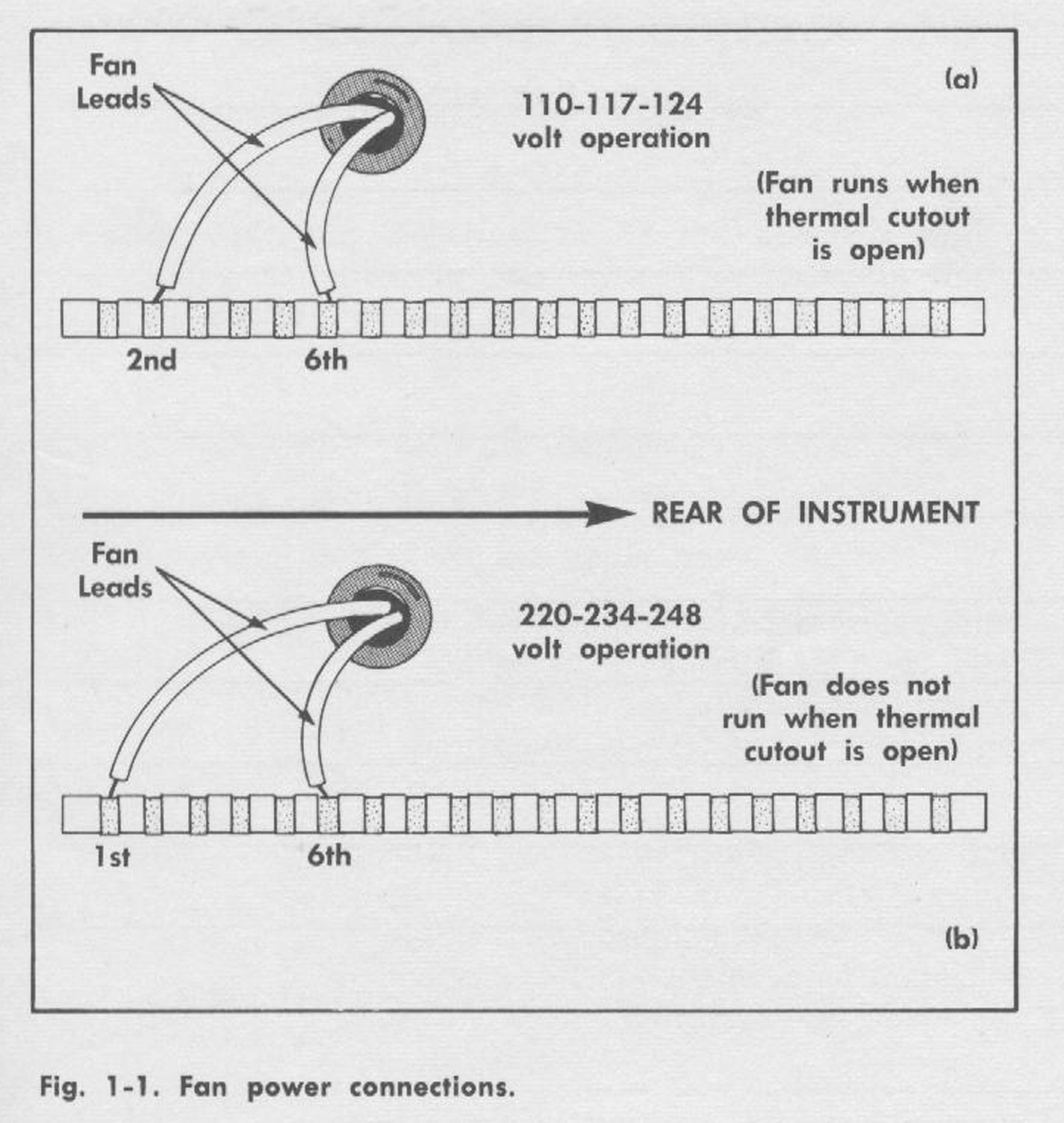
The instrument is wired for the design-center line voltage indicated on a metal tag on the instrument rear panel. Changes can be made in the internal wiring to permit operation with design-center line voltages of 110, 117, 124, 220, 234, or 248 volts. The transformer primary connections for each voltage is indicated on the diagram attached to the power transformer. Fan connections are indicated in Fig. 1-1. The line fuse (on the front panel) is a 6.25 amp slow-blowing type for110, 117, 124 volts and 3 amp slow-blowing type tor 220, 234, and 248 volts.Line Frequency
50 to 60 cycles.
Power Consumption
Maximum of about 600 watts including plug-in unit power
consumption and excluding loads connected to the AUX.
POWER JACK.
Ventilation
Forced filtered air. The self-resetting thermal relay interrupts instrument power in the event of overheating. In
instruments equipped with ac fans, the fan will continue to run during thermal interruption if the instrument is wired tor design-center line voltages of 125 vac and below.
Construction
Four-piece, blue vinyl finished cabinet, aluminum-alloy chassis, and photo-etched, anodized front panel.
Dimensions
Width: 17 inches
Height: 13½; inches
Depth: 233/8 inches
Weight: 62 pounds»
§§§
Il testo prosegue nella quarta parte.
Per consultare le altre  schede dedicate a questo oscilloscopio esposto al Museo MITI (su proposta di Fabio Panfili) scrivere “565” su Cerca.
Elaborazioni  e testo a cura di Fabio Panfili.
Per ingrandire le immagini cliccare su di esse col tasto destro del mouse e scegliere tra le opzioni.


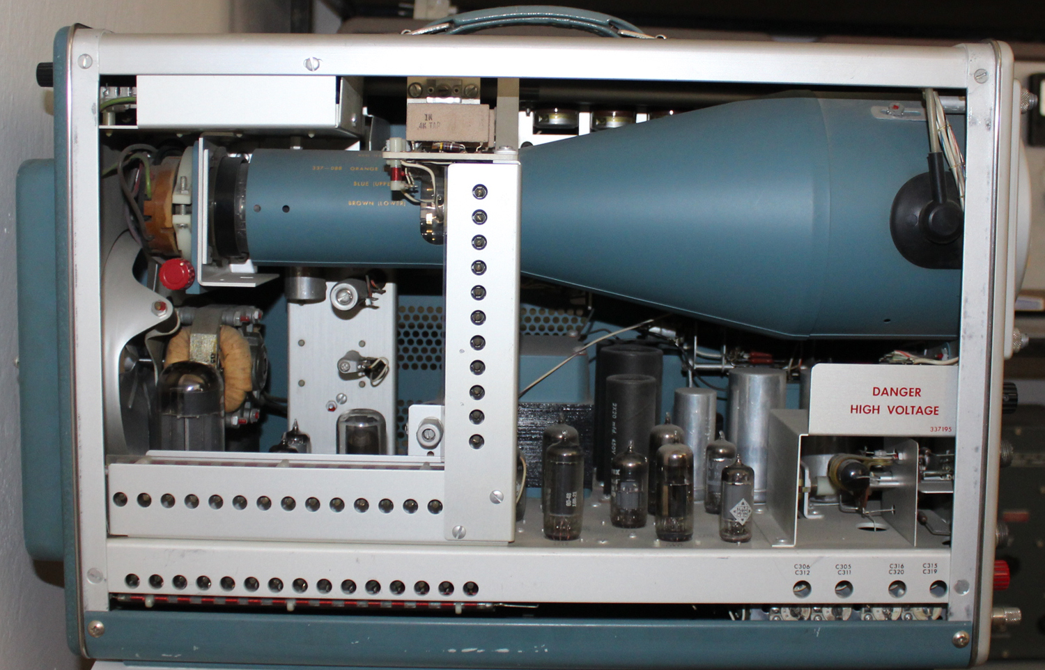
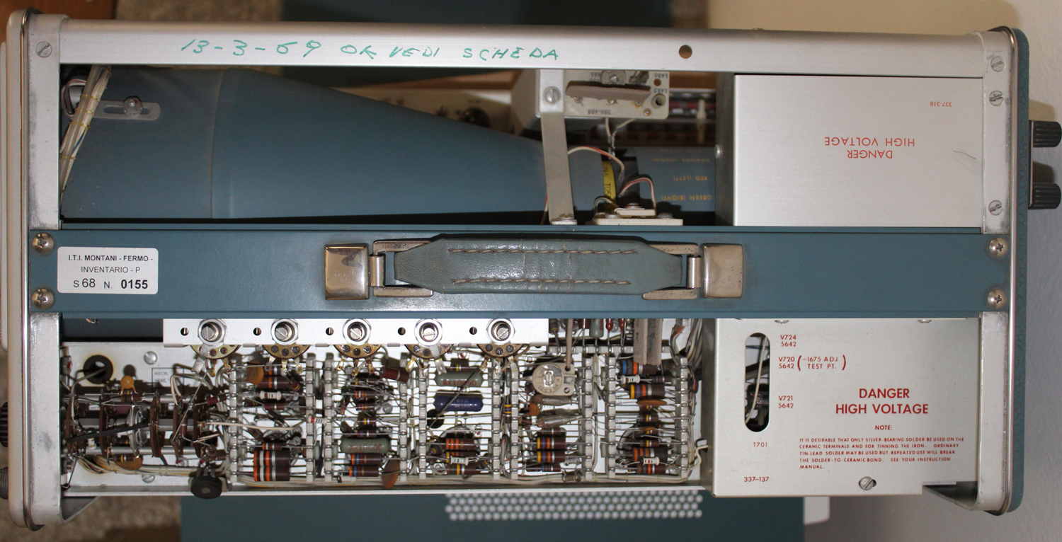
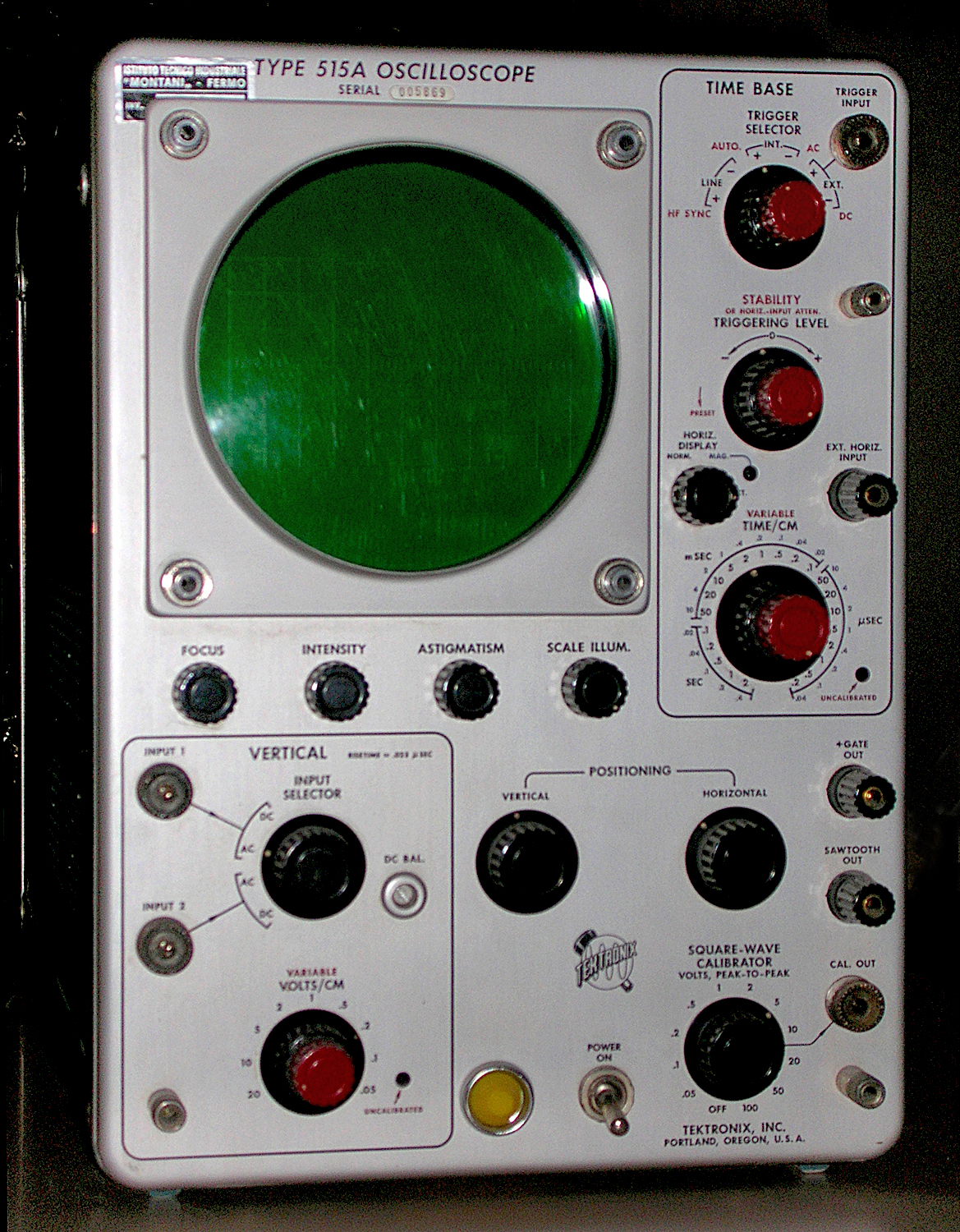
Oscilloscopio Tektronix type 515A matr. 005869 5ª parte


Oscilloscopio a tubo catodico Tektronix Type 515A serial 005869. Quinta parte.
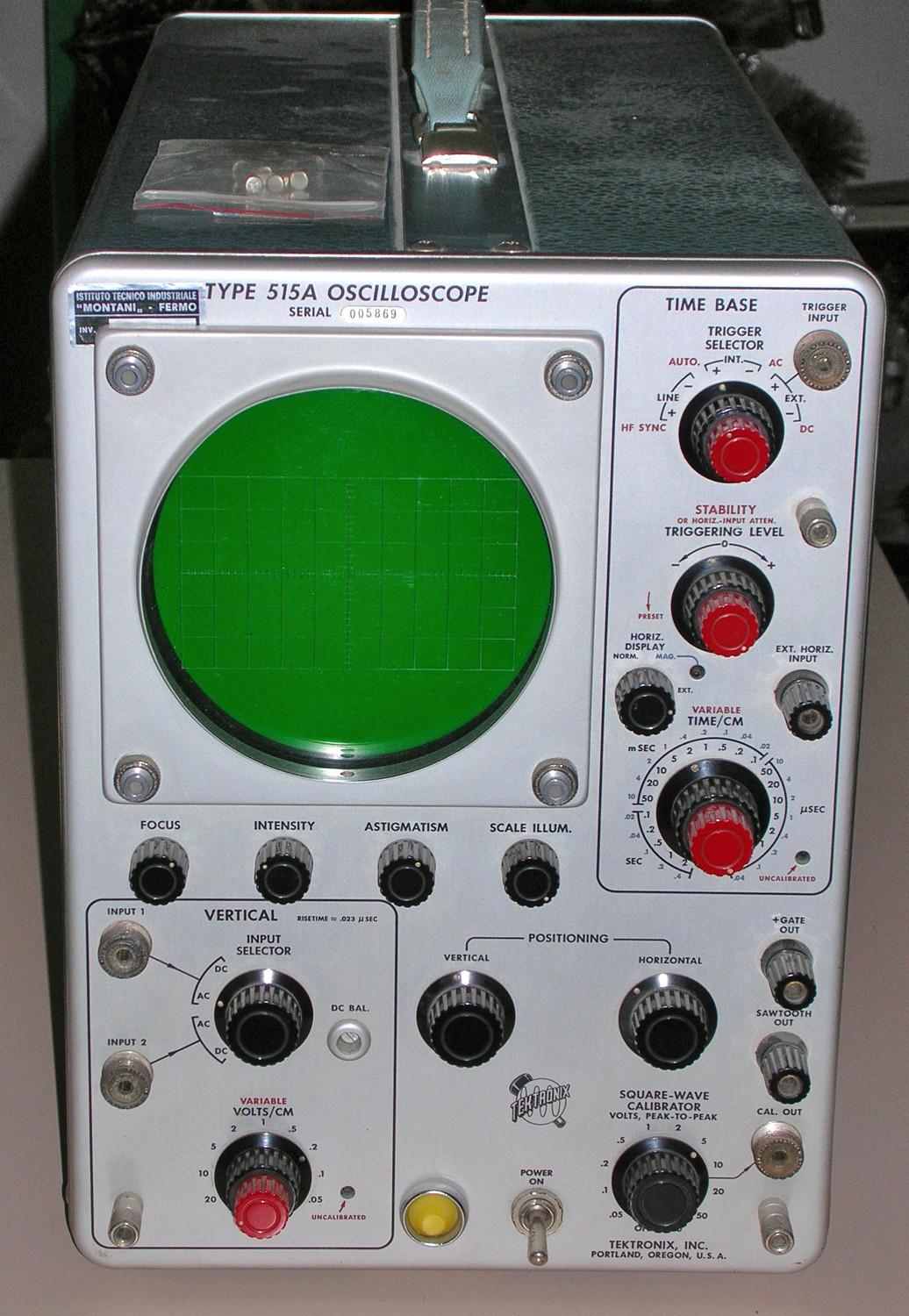
 Della Tektronix, Inc. Portland, Oregon, Usa.  Nell’inventario D del 1956, in data aprile 1961, al n° 1899 si legge: ”Imp. Silvestar-Milano – Oscilloscopio Tektronix tipo 515A. Destinazione Elettronica. ₤ 840000”.
Il testo continua dalla quarta parte.
§§§

«Schmitt Multivibrator
The dc-coupled multivibrator, shown in the
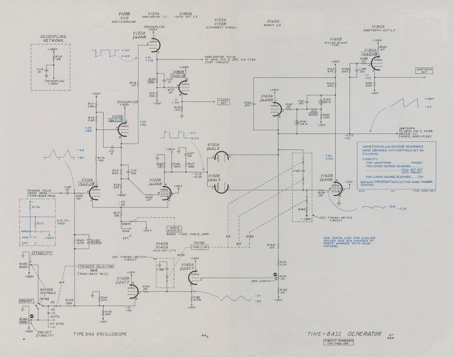
time-base diagram, turns on the time-base generator upon receipt of a negative trigger from the trigger shaper, and holds off subsequent trigger signals until after the sweep is completed. The multivibrator consists of V110A and V120 with both common-cathode and plate-to-grid coupling. Plate-to-grid coupling is by means of a cathode follower.
In the quiescent state V110A is conducting and its plate is down. Cathode-follower V110B holds the grid of V120B below cutoff through voltage divider R115 , R116. Cathode-follower V110B isolates the plate of V110A from the
various loads, and thereby permits a faster
step.
When the negative trigger pulse from the trigger-shaper stage reaches the grid of V110A it is coupled to V120B and V120B starts to conduct. The multivibrator switches quickly to its second state with V120B conducting and V110A cut off. The biases and plate loads are adjusted so that when V110A is conducting, the grid of V120B is held below cutoff, and when V120B is conducting the cathode of V110A is held above cutoff.
There are thus two stable states, in either of which the multivibrator will remain until a signal of the proper polarity and amplitude to the grid of V110A switches it to the other state. To return the multivibrator back to
the quiescent state with V110A conducting, a positive voltage is required at the grid of V110A which is high enough to cause plate current to flow. The positive voltage for returning the multivibrator to its quiescent state is supplied from the time-base generator when it has completed its sweep.
The STABILITY and PRESET controls adjust the grid voltage of V110A near the point of free running.
Time- Base Generator
The time-base generator is a Miller integrator
circuit. The circuit includes disconnect diodes V150A and V150B, cathode-follower V160A, timing capacitor C160 and the Miller tube, V160B. In the quiescent state between sweeps, the plates of diodes V150A and V150B rest at -2.5 volts. Very little current flows through V150B to the grid circuit of V160B, and the
grid of V160B rests at -2.5 volts. More current flows through V150A so that its cathode is about .5 volt lower at -3 volts. The timing capacitor, C160, which is connected between these two points, therefore has a charge of
about .5 volt.
The grid of cathode-follower V160A is
connected to the plate of Miller tube V160B through neon glow tube B160. The grid of V160A therefore follows the plate changes of V160B but remains 55 volts below the plate. Network C161, R161, improves the risetime of the circuit.
The -2.5 volt bias on the grid of V160B places the tube in the class A region of its operating characteristic, where the plate-to-cathode voltage is inversely proportional to the grid to cathode voltage. The plate rests at about +55 volts. The negative step from the multivibrator to the plates of diodes V150A and V150B lowers the plates below their cathodes
and they no longer conduct. The Miller-tube grid, and the cathode follower are thus released to seek their own voltage levels. The grid of Miller tube V160B, which is returned to
-150 volts through R150, starts negative. When the grid starts negative the plate starts-positive carrying cathode-follower V160A grid and cathode positive. This raises the top end of C160 positive which thus tends to prevent the Miller tube grid from going negative.
The gain of the Miller tube as a class-A amplifier is so high that the plate signal coupled back through charging capacitor C160 keeps the grid voltage constant within a fraction of a volt. Meanwhile, C160 is charging with current through R150 from the -150-volt bus.
Since the grid of V160B remains constant within a fraction of a volt, the current through R150 remains constant, and C160 thus charges at a constant rate. As C160 charges the voltage of the upper end therefore rises linearily.
Any departure from a linear rise of the cathode of cathode follower V160A will result in a change in Miller-tube grid voltage in the direction that will correct for the error. A bootstrap capacitor, C165, increases the plate current in V160B at the higher sweep speeds to help maintain a linear voltage rise.
The linear rise of the cathode of V160A
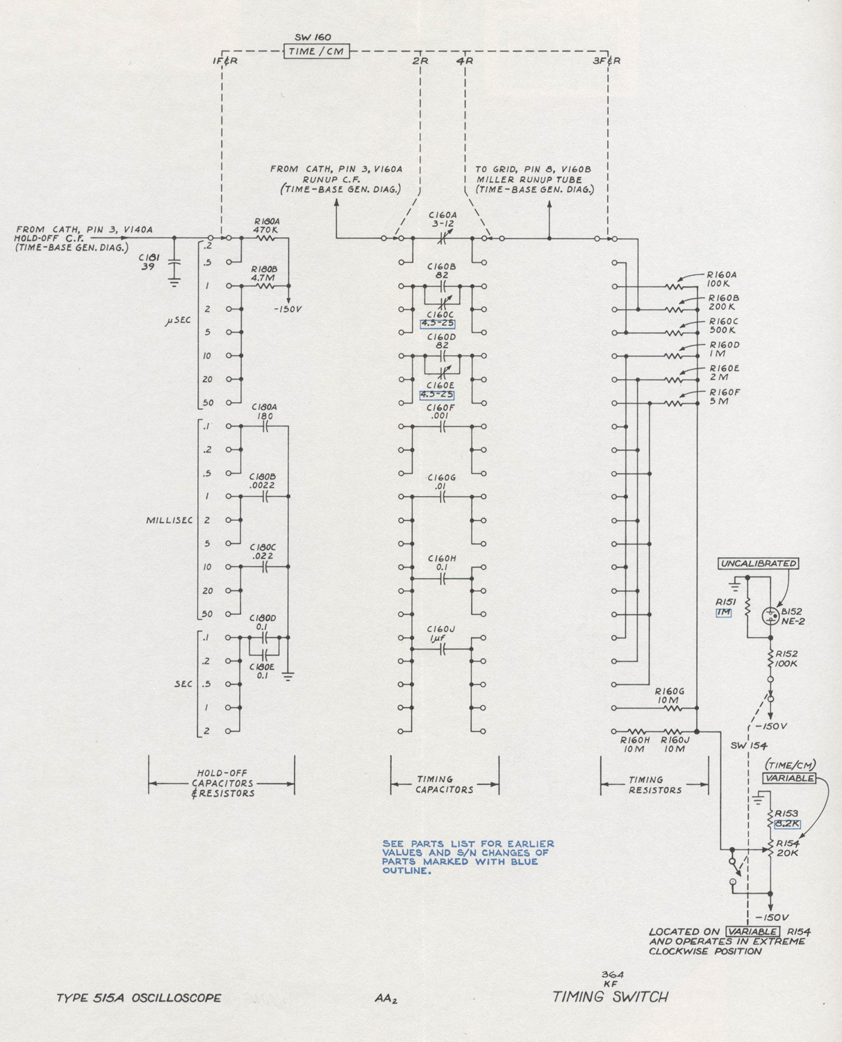
is used as the time-base sawtooth. Charging capacitor C160 is selected by means of a step switch, SW155, labeled TIME/CM on the front panel. Charging resistor R150 is also selected by the TIME/CM switch so that both the size of the capacitor being charged and the current charging the capacitor can be selected to cover a wide range of sawtooth slopes.
The cathode of V160A continues to rise linearly until a positive step from the multivibrator, V120B, returns the disconnect diode plates back to their quiescent state raising
the Miller tube grid. When the Miller tube grid rises, its plate drops carrying cathode-follower V160A with it until its cathode clamps again through V150A at the quiescent level of -2.5 volts. The Miller-tube plate will always rest at about +55 volts after the sweep, because, as V150A begins to conduct, its plate drops slightly. This reduced plate voltage allows the Miller-tube grid to go slightly more negative, stopping the fall in plate voltage.
Sawtooth Amplitude
The positive step from multivibrator V120B,
which stops the sweep, occurs when a positive voltage is delivered to the grid of multivibrator V110A. The time-base sawtooth is applied to the multivibrator through cathode followers V140A and V140B from a tap on the cathode- load resistor of V160A. This tap is adjustable by means of potentiometer R156, labeled Sawtooth Amplitude, a screwdriver adjustment.
When the voltage of this tap is properly set, the sawtooth will terminate when the spot has passed the right-hand limit of the graticule.
C130 on the grid of V140B retards the return of V140B grid to the quiescent level after the passage of the positive voltage. This prevents any trigger signals from retriggering the multivibrator until all other capacitances in the circuit have had time to reach their quiescent voltage levels. Proper sizes of capacitor C131 are switched with the TIME/CM switch so that more recovery time is permitted for the slower sweep rates and the least necessary recovery time is allowed for the faster sweep rates.


Horizontal Amplifier
The time-base waveform passes through the
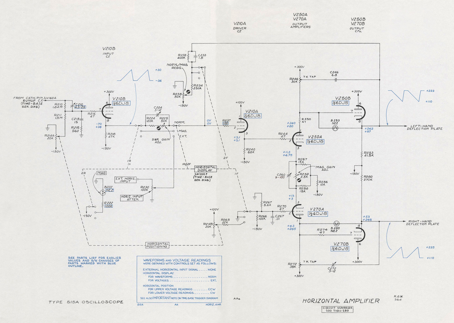
frequency-compensated positioning network, R210, R211, to the grid of cathode-follower V210B. This cathode follower provides the necessary low impedance to drive the switch capacitances and the second cathode follower, V210A. In the NORM. position of the HORIZ. DISPLAY switch, an attenuation network is inserted between the cathode of the Input C.F., V210B and the Driver C. F., V210A. In the MAG. position of the HORIZ. DISPLAY switch, this attenuator network is bypassed, so that the amplitude of the input signal to the Amplifiers is multiplied by a factor of five. In the EXT position, the HORIZ. DISPLAY switch connects the amplifier to the EXT. HORIZ. INPUT binding post to display the signal applied to this binding post.
Cathode-follower V210A applies the signal to the output amplifier, V250A and V270A.
The output amplifier, converts the signal for
push-pull application to the deflection plates. R259 varies the degeneration in the cathode circuits to set the gain of the amplifier. C260 provides high-frequency compensation of the output amplifier by reducing the high-frequency
degeneration. R214B provides horizontal positioning when the HORIZ. DISPLAY switch is in the EXT. position.
The waveform at the plates of the output amplifier is applied to the crt horizontal-deflection plates via cathode followers V250B and V270B. Bootstrap capacitors C246 and C272 increase the current in the output amplifiers at the high sweep rates to improve time-base linearity. Neon diodes B253 and B280 protect the cathode followers from excess grid to cathode voltage when the instrument is first turned on.

CALIBRATOR
The calibrator is a symmetrical multivibrator
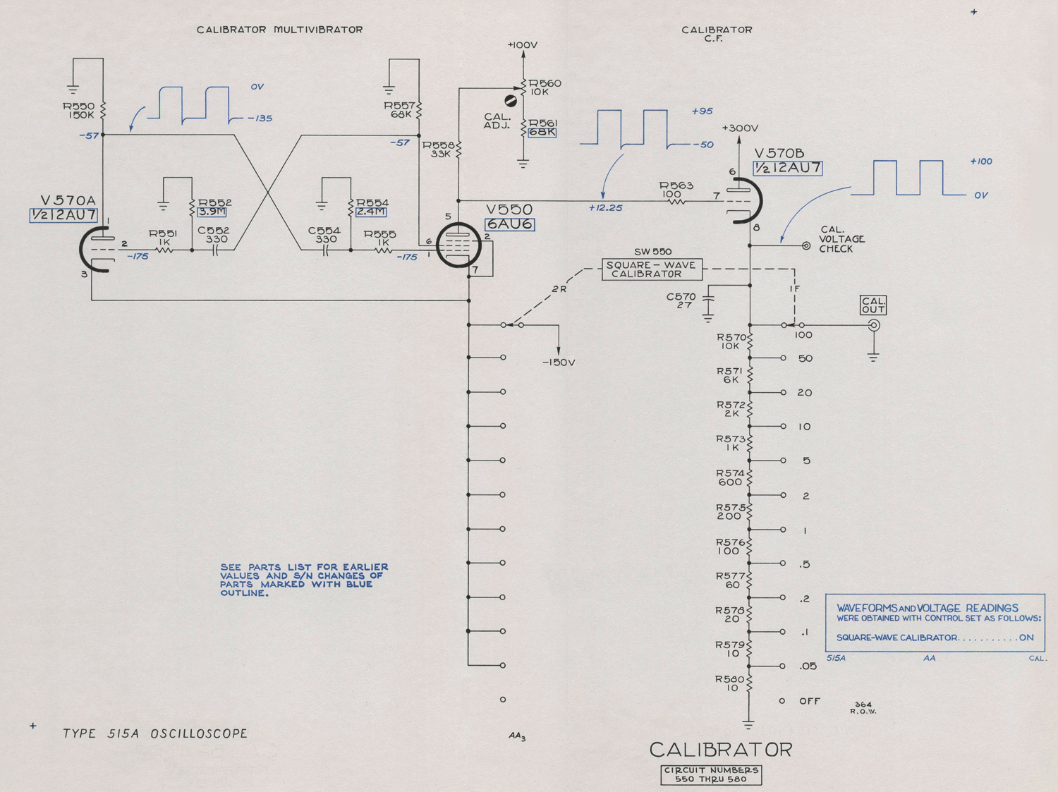
with V550A and V550B connected so as to turn cathode-follower V570 on and off as it oscillates. During the negative pulse at multivibrator V550A, the grid of the cathode follower is driven well below cutoff , so the cathode is at ground voltage. During the positive pulse at the multivibrator, the plate is cut off and rests slightly below +100 volts. The voltage of the plate during cutoff is determined by the setting of R560, part of a divider between + 100 volts and ground. R560 is a screwdriver adjustment labeled CAL. ADJ.
Cathode follower V570 has a tapped, calibrated voltage divider for its cathode resistor. When the CAL. ADJ. control is properly set, the cathode-follower cathode is at +100 volts when V510B is cut off. The taps on the divider provide eleven fixed calibrated amplitudes. No internal connection from the calibrator to the vertical-deflection circuits is provided.

POWER SUPPLY
Transformer
Plate and heater power for the Type 515/515A
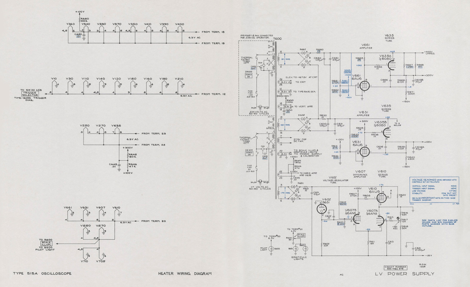
is provided by a single power transformer, T600. The transformer has two equal 117-volt windings that can be connected either in parallel for 117-volt operation, or in series for 234- volt operation.
Rectifiers
The ac voltage from the high-voltage windings
is rectified by bridge-connected full-wave selenium rectifiers.
-150 Volt Supply
All dc voltage furnished by the power supply
are regulated with the exception of the +360-volt supply which is used only to supply circuits which are insensitive to voltage variations.
Reference voltage for the regulators is established by means of a gas-diode voltage reference tube, V602. The voltage-reference tube determines the grid voltage of a comparator amplifier, V607, in the -150-volt supply.
The grid potential of V607B is compared with the voltage obtained from a divider, R616, R617, R618, between the -150-volt bus and ground. R617, labeled -150 ADJ., determines the percentage of the total voltage that appears
at the grid of V607A and thus determines the total voltage across the divider.
The voltage difference between the two grids of V607 appears as an amplified error signal at the plate of V607B. The amplified error signal is dc coupled to the grid of the series-regulator tube, V610. This dc-coupled error signal controls the plate resistance of the
series regulator tube, changing it in the rightdirection to compensate for any change in output voltage. C613 increases the ac gain
of the feedback loop to reduce the ripple.
The screen of V607B has a small amount of the ripple that exists ahead of the series regulator tube connected to it through R605.
The phase of this ripple is such as to reduce
the ripple of the -150-volt bus. This circuit also improves the regulation in the presence of line-voltage variation. R620 bypasses the series tube to reduce the amount of load current through it.
+100-Volt Supply
The -150-volt supply serves as reference
voltage for the +100-volt supply. The voltage at the tap on the voltage divider, R639, R640, is applied to the grid of V631. The error signal is amplified in V631 and applied to the grid of V635B, the series-regulator tube, R633, at the screen of V631, reduces ripple and improves the regulation of the supply. C636 increases the ac gain of the feedback loop.
+300-Volt Supply
Rectified voltage from terminals 8 and 9
of the power transformer is added to the voltage supplying the +100-volt regulator to provide about 400 volts for the +300-volt regulator and other points in the instrument which do not ned a regulated voltage. The +300-volt circuit is similar in operation to the + 100-volt regulator.

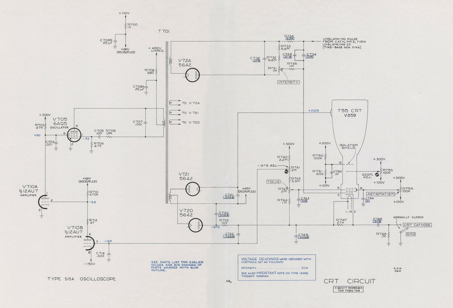
CRT CIRCUIT
High-Voltage Supply
Accelerating voltage for the cathode-ray tube is obtained by rectifying a 60-kc voltage produced by a vacuum—tube oscillator. V705 is the oscillator tube with the primary of T701 serving as a tapped inductor. Rectifier V720 supplies -1675 volts to the crt cathode and V721 supplies +2325 volts to the post-acceleration helix to provide a total acceleration voltage of 4000 volts.
High-Voltage Regulator
A divider from the crt cathode to the +300-
volt bus applies a sample of the negative accelerating voltage to the grid of V710B. R741 varies the voltage at the tap to adjust the high voltage. The -150-volt supply,connected to the cathode of V710B, serves as a reference voltage. The amplified error signal at the plate of V710B is applied to the grid of the shunt regulator tube, V710A. The shunt regulator tube determines the screen voltage of the oscillator tube and thus controls the oscillator output voltage.
If, for example, the output voltage becomes
too high, the regulator reduces the voltage on the screen of the oscillator tube. The output voltage of the oscillator decreases and the output voltage is corrected.
Unblanking
The crt control-grid voltage is produced by a winding and rectifier, V724, similar to
the cathode supply but insulated from it. The positive end of the control-grid supply is connected to the unblanking cathode follower.
When the unblanking pulse is produced at the cathode of the unblanking cathode follower, it drives the whole grid-voltage supply with it so that the pulse appears at the crt grid. Since this is a dc connection, the unblanking pulse can have any duration with no change in grid voltage. The INTENSITY control, R731, varies the bias on the grid to determine trace brightness.
CRT Geometry Control
The second-anode voltage required for best
linearity at the extremes of deflection may vary somewhat between tubes. R753, labeled GEOM. ADJ. on the chassis, permits this
voltage to be adjusted».

§§§
Per consultare le parti dedicate a questo oscilloscopio scrivere: “515A” su Cerca.

Foto di Claudio Profumieri, elaborazioni, ricerche e testo a cura di Fabio Panfili.
Per ingrandire le immagini cliccare su di esse col tasto destro del mouse e scegliere tra le opzioni.


.


Oscilloscopio Tektronix type 515A matr. 005869 4ª parte

Oscilloscopio a tubo catodico Tektronix Type 515A serial 005869. Quarta parte.
 Della Tektronix, Inc. Portland, Oregon, Usa.  Nell’inventario D del 1956, in data aprile 1961, al n° 1899 si legge: “Imp. Silvestar-Milano – Oscilloscopio Tektronix tipo 515A. Destinazione Elettronica. ₤ 840000”.
Il testo continua dalla terza parte.
§§§
                        «SECTION 3
CIRCUIT
DESCRIPTION

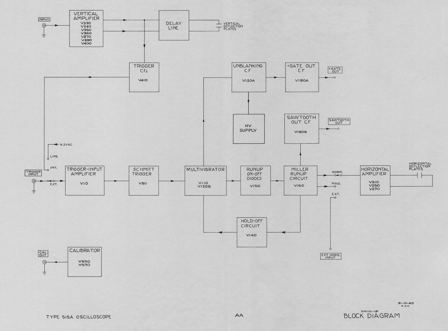
    BLOCK DIAGRAM DESCRIPTION
The block diagram shows the interconnection
of the functional parts of the oscilloscope, except the power supplies. Functions of the switches are shown instead of their actual connections. This diagram, as well as the ones which follow, is designed to fold out so that the diagram can be studied along with the text without turning any pages.
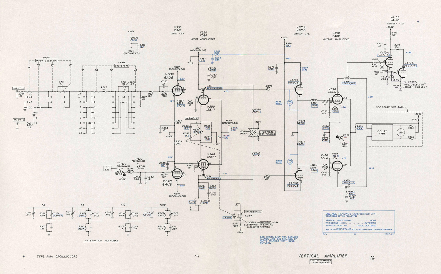
The vertical amplifier has a sensitivity of .05 volt per centimeter (.1 volt per centimeter S/N 101-1000) and provides push-pull output to drive the deflection plates. The balanced
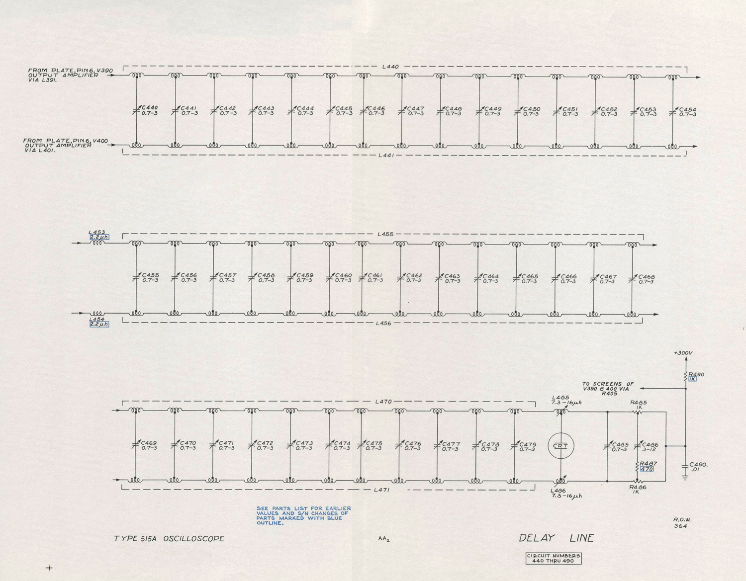
delay line is connected between the output amplifier and the deflection plates.
The trigger cathode follower applies a sample of the vertical signal to the trigger-amplifier stage to provide internal triggering.
The trigger amplifier and shaper provide a sharp trigger pulse which triggers the multivibrator. The multivibrator gates the time-base generator and is prevented from recycling by the holdoff cathode follower until the generator has had time to run up and return.
The time-base generator is a Miller run-up type and provides a 150-volt sawtooth for the horizontal amplifier.
The horizontal amplifier converts the time-base
sawtooth for push-pull applications to the deflection plates.
The unblanking cathode follower applies a positive gate to the crt grid via the high-voltage power supply. It also supplies a gate to the gate-out cathode follower which provides a positive gate at a front-panel binding post.
The calibrator provides a square wave of known amplitude for checking the gain of the oscilloscope amplifiers and auxiliary equipment.

VERTICAL-DEFLECTION SYSTEM
General
The Type 515/515A vertical amplifier has a maximum sensitivity of .05 volt per centimeter (.1 volt per centimeter S/N 101-1000), ac or 1.The circuit consists of two stages of amplification, each stage preceded by cathode followers.
Input Connectors
There are two input connectors which can be switched into the input circuits by SW 301, the INPUT SELECTOR switch. This switch is wired physically so as to reduce coupling between inputs to a minimum. Blocking capacitor C301 is shorted out in the DC positions of the selector switch.
lnput Attenuators
The VOLTS/CM switch inserts frequency-compensated attenuators into the input circuit. Four attenuators are used singly or in tandem pairs to produce nine fixed sensitivities.
DC Balance
The DC BAL control, R338, provides an adjustable, dc grid voltage for V340 so that the cathode of V360 is at the same potential as the cathode of V350. When this control is properly set, no change in vertical positioning will result when the VARIABLE position is rotated.
Input Cathode Follower
The input cathode follower, V330, isolates the input circuits from changes in capacitance as the VARIABLE control is rotated. R330 is a current-limiting resistor to limit grid current in the event an excess voltage is applied to the input. The opposite cathode follower, V340, balances the drift in V330 caused by heater-voltage changes.
Input Amplifier
The input amplifier stage is a common- cathode phase-splitter amplifier. Coils L351 and L361 provide high-frequency peaking. The VARIABLE VOLTS/CM control, R356, varies the gain by varying the degeneration in the
cathode circuit.
Vertical positioning is produced by two dual potentiometers, R368, connected to the plates of the amplifier so that current through one plate load is increased as current through the other plate load is decreased. Since the
amplifier is dc coupled, the change in the plate voltage which occurs changes the position of the trace on the cathode-ray tube.
The rc networks, R352, C352 and R362, C362, provide compensation for the reduction in gain at very-low frequencies which is a characteristic of high-conductance amplifiers.
Output Amplifiers
Cathode followers V370A and V370B drive the output amplifiers through series peaking coils L390 and L400. The GAIN ADJ. control, R396, sets the gain of the amplifier to agree with the front-panel calibration. Plate current
for the output amplifiers is supplied by the delay-line termination resistors , R485 and R486.

Delay Line
The balanced delay line delays the signal until the sweep starts and the crt is unblanked.
The trigger signal is taken from a coil which serves as the first section of the delay line.
Each section of the line is turned for optimum response to a square wave.
HORIZONTAL-DEFLECTION SYSTEM
Trigger Amplifier
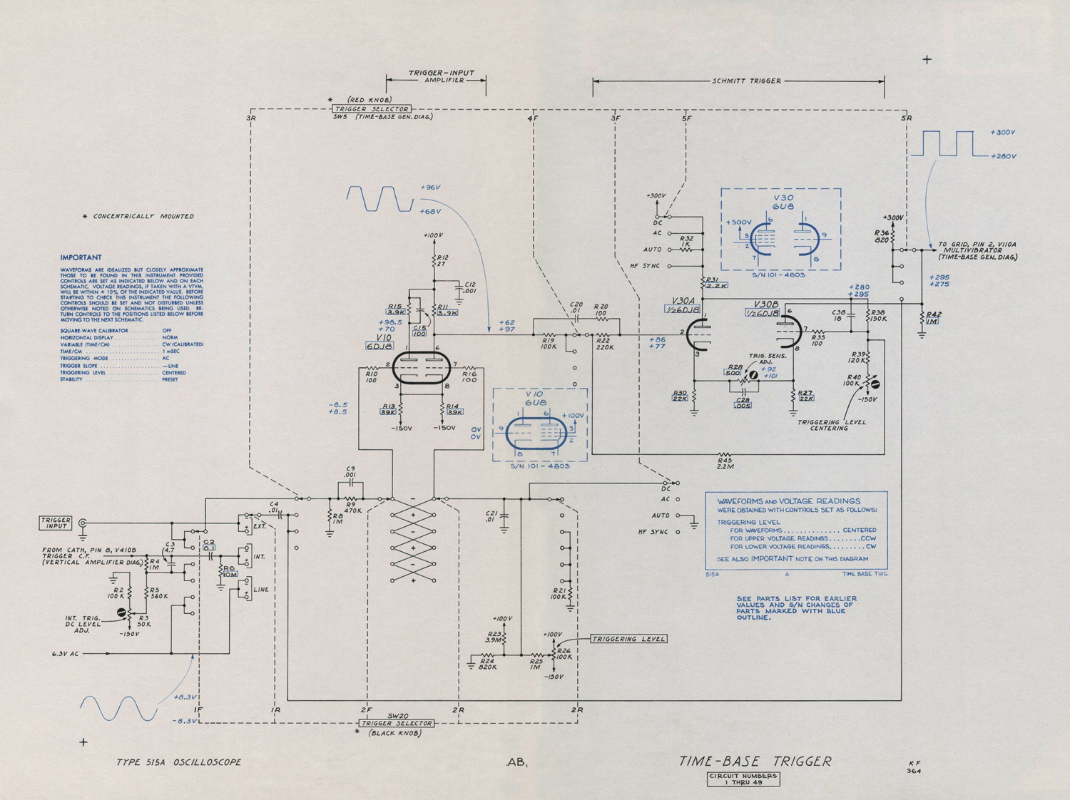
The TRIGGER SELECTOR switch with the black knob, SW20, selects the source of triggering voltage and arranges the trigger-amplifier input circuit to produce negative-going output for either negative-going or positive-going
portions of the input signal.
The trigger amplifier, V10, is a grounded-grid cathode-coupled amplifier. A capacitor, C4, can be switched into the grid circuit to remove the dc component of the trigger signal.
Output is always taken from the pentode plate, but the TRIGGER SELECTOR switch connects either the pentode grid or the triode grid to the input-signal source. The opposite grid is connected to a dc bias source, adjustable by
means of the TRIGGERING LEVEL control.
This bias voltage determines the voltage on the pentode plate. In the AC and DC positions of the TRIGGER SELECTOR switch, the voltage on the pentode plate is dc coupled to the grid of  V30A.
Trigger Shaper
The trigger-shaper stage consists of  V30 connected as a dc-coupled multivibrator. In the normal, or quiescent, state the V30A section is conducting and its plate is down. The grid
of the V30B section is dc coupled to the V30A plate through divider R38, R39 and R40, which holds the “B” grid below plate-current cutoff.
As the trigger signal drives grid of V30A in the negative direction the cathodes of both tubes follow the grid down until V30B starts to conduct. At this point the plate voltage of V30A and the B grid rises with it. The V30B cathode rises with its grid carrying the “A” cathode with it and V30A cuts off.
The transition occurs very rapidly, regardless of how slowly the V30A grid signal falls.
The steep negative-going step at the plate of V30B is differentiated by an rc network including C109 shown in the sweep diagram, and the sharpened pulse trips the sweep multivibrator.

Trigger Mode Switch
The TRIGGER SELECTOR switch with the red knob, SW5, has four positions which arrange the circuits for four types, or modes, of triggering. In the DC position, the triggering signal is dc coupled as far as the trigger-shaper
stage. In the AC position, blocking capacitor C4 removes the dc component of the signal.
In the AUTO. position of SW5, the plate of the A section of the trigger shaper, V30, drives the grid of the B section just as it also drives its own grid through R45 , a resistance of several megohms. This plate-to-grid coupling allows the trigger shaper to free-run when no triggering signal is present. The presence of R45 causes the trigger shaper to free run when no trigger signal is present. For example,
when the plate of V30A rises, the grid of V30B also rises, carrying with it the right-hand end of R45. The left-hand end of R45 is connected to the A grid through R22. The
time constant of the rc circuit between the B grid and ac ground through C20, R22 and R45 is of such length that it takes about .01 second for the V30A grid to rise exponentially from its starting point below cutoff to a point where plate current can flow.
When V30A plate current flows, the plate drops, forcing the V30B grid down, and thus the right-hand end of R45 is forced down.
The left-hand end of R45 and the A grid immediately begin to drop exponentially toward cutoff. When the A grid reaches cutoff again it has completed one cycle of the approximately 50-cycle triangular waveform. The range of
the V30A grid voltage between A cutoff and B cutoff is about 3 volts for the circuit used in the AUTO. mode. This is increased from about .5 volt for the AC and DC modes by the addition of R45 to the circuit.
Since the V30A grid is never more than 3 volts from cutoff, a trigger signal with a peak-to-peak voltage of three volts or more can drive the grid to cutoff at any time and produce a trigger output. Smaller signals can also trigger the shaper but only if they occur at a time when the grid is within their peak voltage of cutoff. The duty cycle of operation of the time-base generator is somewhat reduced therefore with smaller trigger signals.
This circuit configuration is useful because with it the time-base generator can be synchronized with repetitive signals over a wide range of frequencies without readjustment. When not triggered externally, the generator continues at a 50-cycle rate, and in the absence of any vertical signal, generates a base line that shows that the oscilloscope is adjusted so as to display any signal that might be connected to the vertical-deflection system.
In the H F SYNC position of SW5, the trigger amplifier and trigger shaper stages are bypassed and the trigger signal is applied directly to the sweep multivibrator. In this mode the STABILITY control is set so the sweep is superimposed on the negative-going trigger-holdoff waveform at the grid of V110A and will cause the multivibrator to synchronize at a submultiple of the triggering signal frequency. This circuit is suitable for signals in excess of five megacycles.»
§§§
Il testo prosegue nella quinta parte.
Per consultare le parti dedicate a questo oscilloscopio scrivere: “515A” su Cerca.
Foto di Claudio Profumieri, elaborazioni, ricerche e testo a cura di Fabio Panfili.
Per ingrandire le immagini cliccare su di esse col tasto destro del mouse e scegliere tra le opzioni.
Oscilloscopio Tektronix type 515A matr. 005869 3ª parte


Oscilloscopio a tubo catodico Tektronix Type 515A serial 005869. Terza parte.

 Della Tektronix, Inc. Portland, Oregon, Usa.  Nell’inventario D del 1956, in data aprile 1961, al n° 1899 si legge: “Imp. Silvestar-Milano – Oscilloscopio Tektronix tipo 515A. Destinazione Elettronica. ₤ 840000”.
Il testo continua dalla seconda parte.
§§§
«Stability
The STABILITY control adjusts the bias level on a multivibrator in the time-base generator near the level at which the sweep will free-run. Three principal settings of the STABILITY control are used; the first setting is with the control advanced to the right, past the point where the generator free-runs; second, retarded to the left just past the point where free-running ceases; and third, retarded all
the way left to make the generator inoperative.
The second setting is duplicated by an internal circuit when the STABILITY control is rotated to the PRESET position.
When the time-base generator free-runs, the sawtooth waveforms are produced at a repetition rate determined by the generator circuit itself. The STABILITY control varies
this repetition rate slightly. In the second, or triggered, position of the STABILITY control the time-bas; generator does not run until a trigger pulse is received at which time one sawtooth waveform is produced and the generator waits for the next trigger pulse.
This is also the case when the STABILITY control is set at PRESET.
For synchronized operation of the time-base generator, as used in the H F SYNC position, set the STABILITY control to the advanced position so that the generator just free-runs,
and keep it to the right of this point while adjusting its point to synchronize the time base.
For all triggered operation except AUTO., the STABILITY control should be retarded to the left of the free run point or set to the PRESET position (S/N 1001-up).
General-Purpose Triggering
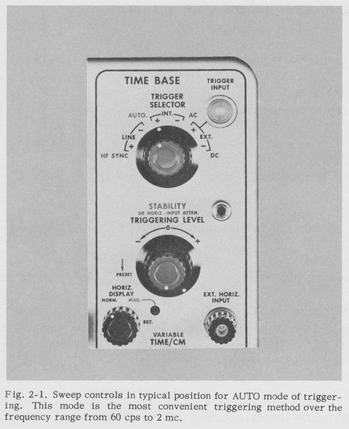
For most average triggering applications the AUTO. mode of triggering is the easiest to use. Only one control need be adjusted and after it is once set the sweep will trigger
satisfactorily on a wide variety of waveforms and over a wide range of sweep speeds without resetting. When the STABILITY control is set properly there will always be a trace on the screen, whether a signal is present ornot, unless the trace is positioned off the screen vertically. This feature is especially valuable  if the probe is being moved from
one point to another in a circuit under test.
To use the AUTO. mode, set the red TRIGGER SELECTOR knob to AUTO. A horizontal trace should appear immediately. A stable display should be obtained on most signals within the range of 60 cycles to 2 megacycles when using this mode.
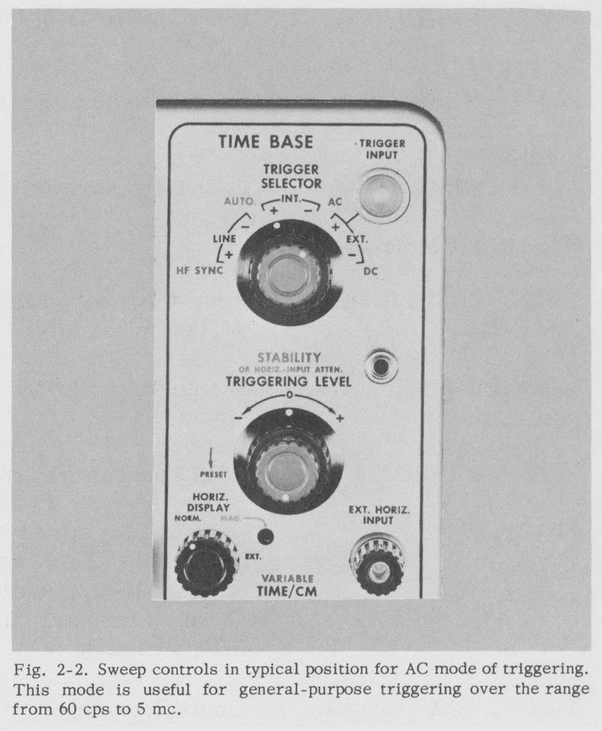
For any application within the frequency range from 60 cycles to about 5 megacycles where the display is unstable on AUTO., the AC mode can be used. To use this mode of
triggering proceed as follows:
1 . Set the red TRIGGER SELECTOR knob to AC.
2. Set the STABILITY C0ntI’01 t0 the PRESET position (counterclockwise S/N 101-1000).
3. Adjust the TRIGGERING LEVEL control for stable triggering. The procedure outlined above will provide
stable triggering for most applications. However, with some triggering waveforms, it may be necessary to manually set the STABILITY control. This is done as follows:
1. Set the red TRIGGER SELECTOR knob to AC.
2. Turn the TRIGGERING LEVEL control counterclockwise to the stop.
3. Advance the STABILITY control clockwise until the time-base generator free-runs then back it off just past the point where the sweep stops.
4. Turn the TRIGGERING LEVEL control clockwise until stable triggering occurs. With this same control you can now select the point or level at which triggering occurs. Triggering should occur near the 0 mark.
Low-Frequency Triggering
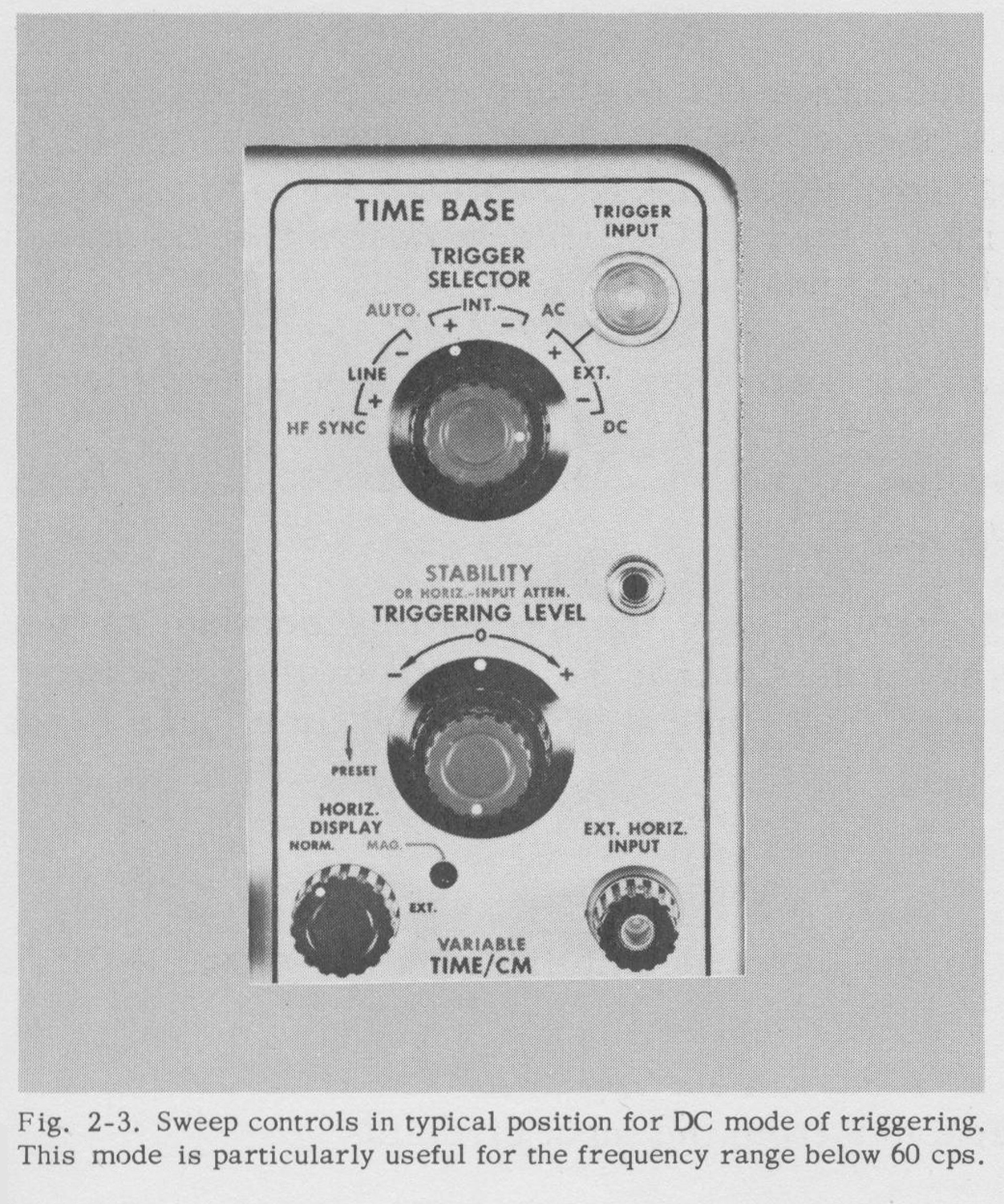
For waveforms having a slow rise and a repetition rate of less than 60 cps, the DC triggering mode is best.
To use this mode of triggering, proceed as follows:
1. Set the red TRIGGER SELECTOR knob to DC.
2. Set the STABILITY control to the PRESET position (counterclockwise S/N 101-1000).
3. Adjust the TRIGGERING LEVEL control for stable triggering. The procedure outlined above will provide
stable triggering for most applications. However, with some triggering waveforms, it may be necessary to manually set the STABILITY control. This is done as follows:
1. Set the TRIGGER SELECTOR red knob to DC.
2. Turn the TRIGGERING LEVEL control counterclockwise to the stop.
3. Advance the STABILITY control clockwise until the time-base generator free-runs then back it off just past the point where the sweep stops.
4. Turn the TRIGGERING LEVEL control clockwise until stable triggering occurs. With this same control you can now select the point or level at which triggering occurs.
Triggering should occur near the 0 mark if the trace is centered. Since the AC mode is more sensitive than the DC mode above 60 cps and is not affected by the positioning controls, it is superior to the DC mode, above 60 cps. However, the DC mode can be used up to about 5 mc.
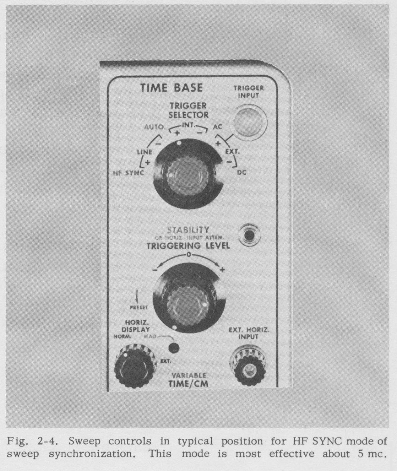
High-Frequency Synchronization
For stable triggering it is necessary for the trigger circuits to have a frequency response considerably in excess of the frequency of the waveform being displayed. At about five
megacycles the efficiency of the trigger circuits is reduced and the H F SYNC mode becomes the best method of synchronizing the trace.
To use the H F SYNC mode simply advance the STABILITY control until the time base free-runs and then continue to advance it until the time base locks in with the signal. The polarity markings on the TRIGGER
SELECTOR switch have no significance in this mode, and the TRIGGERING LEVEL control is not used.
Triggering on Complex Waveforms
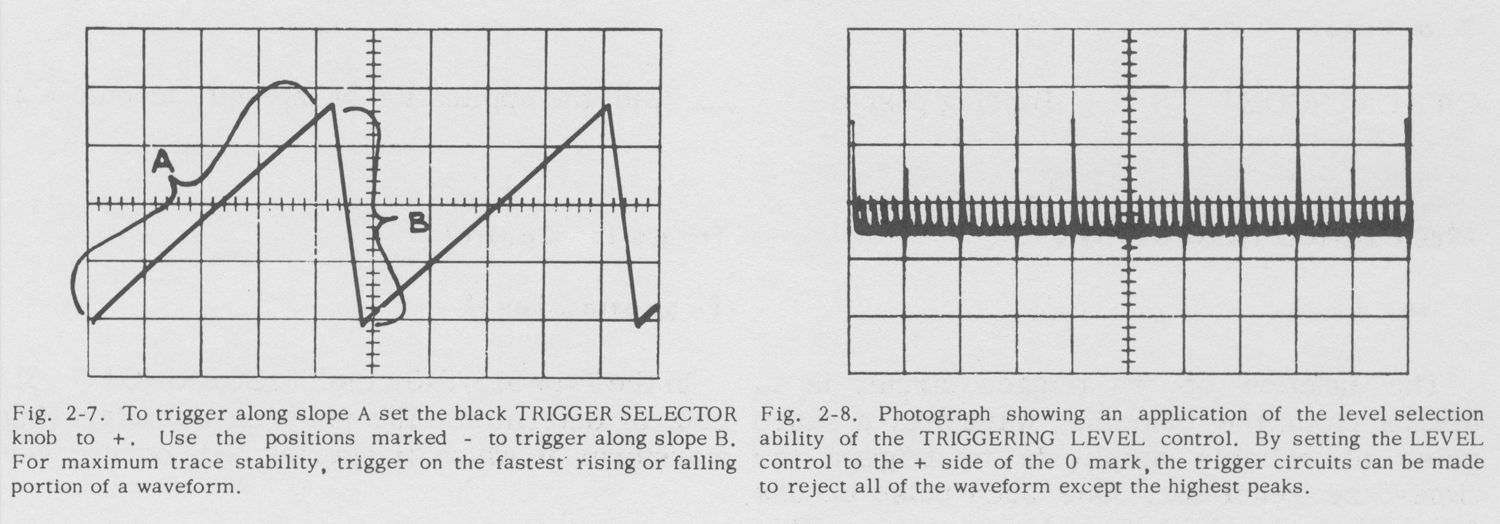
When the waveform under observation is complex there may be several points on the waveform where ordinary triggering circuits may tend to trigger. As a result, the trace
may be unstable. This instability may be encountered occasionally with the AUTO. mode of triggering. The AC and DC triggering modes allow the level on a waveform, at which triggering occurs, to be selected by the TRIGGERING LEVEL control. Thus the LEVEL control can be set so that only one point on the waveform is of sufficient amplitude to trip the triggering circuits. This point can be located by setting the controls as for the AC or DC triggering modes and then moving the TRIGGERING LEVEL control away from the 0 mark in either direction
until the trace becomes stable.
Trigger-Signal Source
For most normal triggering applications the INT. trigger source is most convenient. In the INT. positions of the TRIGGER SELECTOR switch the triggering signal is obtained from the vertical amplifier. If an external trigger source is available it is often convenient to use the EXT. positions of the TRIGGER SELECTOR switch. An external
trigger source is particularly useful if the amplitude of the signal under observation is changing or if the probe is being moved from point to point in a circuit.
The LINE positions of the TRIGGER SELECTOR switch permit stable triggering at the line frequency. These positions are useful when displaying almost any function
that is synchronized with the line. TIME-BASE OPERATION
General
The time-base generator produces the sawtooth waveform which is used to move the beam across the crt. The TIME/CM controls vary the slope, but not the amplitude, of this waveform, and thus determine the sweep rate
without affecting the length greatly.
The horizontal amplifier amplifies the sawtooth waveform and applies it to the crt deflection plates. The HORIZ. DISPLAY switch increases the gain of the amplifier five times in the MAG. position. In this position the display
is spread over the equivalent of five screen diameters.
Sweep Rule
The TIME/CM controls determine the sweep rate of the horizontal trace. The TIME/CM of horizontal deflection is indicated by the black numbers when the HORIZ. DISPLAY switch is in the normal position and by the
blue numbers when it is in the MAG. position.
These numbers are correct only when the red VARIABLE control is completely clockwise.
The UNCALIB RATED light indicates when the time base is not calibrated for this reason. The VARIABLE control has a range of about 2 · 1/2 to 1. [?? N.d.R.]
Magnifier
The HORIZ. DISPLAY switch increases the horizontal-amplifier gain five times in the MAG. position expanding the time base so that the center one-fifth of the trace fills
the graticule. The MAG. light is energized when the HORIZ. DISPLAY switch is turned to the MAG. position. Any portion of the trace may be positioned on the screen with the HORIZONTAL POSITIONING control. If
the VARIABLE control is fully clockwise the magnified sweep rate is indicated by the blue numbers at the TIME/CM switch.
External Horizontal Input
When the HORIZ. DISPLAY switch is in the EXT. position, the horizontal amplifier is connected to the EXT. HORIZ. INPUT binding post. The STABILITY control serves as an
attenuator for signals applied to this bindingpost.
VERTICAL-AMPLIFIER OPERATION
Probes
The P6017 probe furnished with this instrument has a 10 – to – 1 attenuation ratio. Be sure to check the adjustment of the probe regularly and before making critical measurements. If the compensation is incorrect the frequency response will be affected. Touch the probe
tip to the calibrator output connector and display several cycles of the calibrator waveform.
If the top and bottom of the displayed square wave are not flat, adjust the trimmer capacitor located inside the probe compensator box to achieve correct square-wave response.
Input Connections
Be careful that the external circuitry does not cause deterioration of the waveform when you make connections to the INPUT connectors.
Improper termination of cables may cause ringing or loss of frequency response. If you use unshielded leads keep them as short as possible.
Two cables or probes can be connected to the oscilloscope at once. You can then select the signal on either cable with the INPUT SELECTOR switch. However, if one signal
is very much larger than the other, some crosstalk may occur and the cable having the larger signal should be disconnected.
Coupling
It is sometimes unnecessary or undesirable to display the dc level of the waveform. In the two AC positions of the INPUT SELECTOR switch,  a capacitor in series with the input blocks the dc component of the waveform so that only the ac component is displayed.
Deflection Sensitivity
The VOLTS/CM switch inserts frequency-compensated attenuators ahead of the amplifier. The VARIABLE control provides continuous adjustment of the deflection sensitivity between the values indicated by the VOLTS/CM switch.
The VARIABLE control must be clockwise against the stop for the sensitivity to be as indicated by the VOLTS/CM switch. The red UNCALIBRATED light indicates when the
VARIABLE control is not fully clockwise.
DC Balance Adjustment
After the oscilloscope has been in use for a period of time you will notice that the trace will change position as the VARIABLE control is rotated. This is caused by tube aging and the resultant shift in operating potentials. To correct this condition rotate the VARIABLE control back and forth and adjust the DC BAL control until the trace position is no longer affected by rotation of the VARIABLE control. AUXILIARY FUNCTIONS
Square-Wave Calibrator
The square-wave calibrator provides a source of square waves of known amplitude at about 1000 cycles. The outout impedance varies with the voltage but is as high as 5,000 ohms.
Be sure the load impedance you connect to the CAL. OUT connector does not change the output voltage.
Truce-Brightness Modulation
To couple markers or other signals into the crt cathode for brightness information, disconnect the ground strap at the rear of the instrument and connect the signal to the CRT CATH. binding post.
Graticule Illumination
The graticule lighting control, labeled SCALE ILLUM., can be adjusted to suit the lighting conditions of the room. The graticule can be mounted in either of two positions rotated
180 degrees from each other. In one position the illumination is colored red and, in the other position, white. The white will reproduce well photographically.
A green light filter is supplied which can be used for increased contrast. Normally this filter should be mounted next to the crt screen so it does not block the light from the graticulelines.
Direct Connection to Deflection Plates
Connections can be made directly to the deflection plates by removing the cabinet on the left side. The two pins on the left-hand side of the crt neck are the vertical deflection
plates. To avoid distortion, the average dc potential on these plates should be between 150 and 200 volts. Unless dc coupling is required, connect coupling capacitors in series
with the leads to the deflection plates and connect one-megohm resistors from the deflection plates to the leads from the delay line.
With this connection the plates are maintained at the proper operating potential and positioning control is retained by the front-panel controls.»
§§§
Le due figure sono tratte dal capitolo MAINTENANCE che abbiamo omesso.
Il testo prosegue nella quinta parte.
Per consultare le altre schede dedicate a questo oscilloscopio scrivere: “515A” su Cerca.
 Foto di Claudio Profumieri, elaborazioni, ricerche e testo a cura di Fabio Panfili.
Per ingrandire le immagini cliccare su di esse col tasto destro del mouse e scegliere tra le opzioni.


Oscilloscopio Tektronix type 515A matr. 005869 2ª parte


Oscilloscopio a tubo catodico Tektronix Type 515A serial 005869. Seconda parte.
Della Tektronix, Inc. Portland, Oregon, Usa. Nell’inventario D del 1956, in data aprile 1961, al n° 1899 si legge: “Imp. Silvestar-Milano – Oscilloscopio Tektronix tipo 515A. Destinazione Elettronica. ₤ 840000”.
Il testo continua dalla prima parte.
§§§
                                «SECTION II
                                OPERATING
                            INSTRUCTIONS

General information
The Type 515/515A Oscilloscopes are extremely versatile instruments, adaptable to a great number of applications. However, to make use of the full potentialities of the instrument, it is necessary that you understand completely the operation of each control. This portion of the Operators Manual is intended to provide you with the basic information that you require. If you are familiar with other
Tektronix oscilloscopes, you should have very little difficulty in understanding the operation of the 515/515A, since the function of many of the controls is the same as the function of corresponding controls in other Tektronix
instruments.
Cooling
A fan maintains safe operating temperature in the Type 515/515A Oscilloscope by circulating air through a filter and over the rectifiers and other components. The instrument must therefore be placed so the air intake is not
blocked. The air filter must be kept clean to permit adequate air circulation. lf the interior temperature does rise too high for some reason, a thermal cutout switch will disconnect the power and keep it disconnected until the temperature drops to a safe value.
Power Requirements
The regulated power supplies in
the Type 515/515A will operate with line voltages from 105 to 125 volts or from 210 to 250 volts.
For maximum dependability and long tube life the voltage should be near the center of this range.
Voltages outside of these limits may cause hum or jitter on the trace. Be sure the line voltage is correct if indications such as these are present.
Unless tagged otherwise, this oscilloscope is connected at the factory for 117 – volt operation. For 234-volt operation , refer to the Maintenance section of this manual for proper transformer connections.
FIRST-TIME OPERATION
Control Settings
The following procedure will help you get a trace on the screen and become familiar with some of the controls.
Connect the line cord to a source of 117- volt 50 to 60 cycle power, and set the front-panel controls as follows:
FOCUS                                      Centered
INTENSITY                             Counterclockwise (CC W)
ASTIGMATISM                     Centered
POWER                                    ON
INPUT SELECTOR              INPUT 1, DC
VOLTS/CM                              5
(black knob)
TRIGGER SELECTOR
black knob                             + INT
red knob                                  AUTO
TRIGGERING                        Counterclockwise
LEVEL
STABILITY                            PRES ET (CCW S/N
(red knob)                          101-1000)
HORIZ. DISPLAY                 NORM.
TIME/CM                           .5 MILLISEC
VERTICAL                             Center
POSITIONING
HORIZONTAL                      Center
POSITIONING
CALIBRATOR                       10
Connect a lead from the CAL. OUT connector to the INPUT 1 connector. If the tubes have had time to warm up, turn the INTENSITY control clockwise until a trace is visible on the screen. Adjust the FOCUS, ASTIGMATISM
and INTENSITY controls to produce a sharp trace of comfortable brightness.
The two POSITIONING controls will move the trace vertically and horizontally as necessary to position the display where you want it on the crt screen.
Triggering Modes
If you have not had previous experience with the type of trigger controls used on this oscilloscope, the calibrator waveform is a good one to practice with. A few minutes
spent on trying the triggering modes described below will be time well spent in terms of future operating convenience.
Auto
The triggering method used in the preceding example is the AUTO. (automatic) mode of operation. It is the simplest mode of triggering.
There are no front-panel controls to be adjusted when using this mode. If the signal is removed from the input connector, the sweep will continue, but at a reduced repetition rate. This provides a visual indication that the signal has been removed and the sweep and triggering
circuits are operating.
FUNCTIONS OF CONTROLS AND CONNECTORS
CRT Controls
FOCUS                Control to adjust the beam for maximum
sharpness of the trace.
INTENSITY          Control to vary the brightness of the trace.
AC
Now try the AC mode of triggering. Turn the red TRIGGER SELECTOR knob to AC. Advance the TRIGGERING LEVEL control clockwise until you get a stable trace. There
may be a considerable range over which you get a stable trace. The start of the trace will move up and down the edge of the square wave over this range. Notice that the trace
starts on the up-going part of the calibrator square wave.
Now turn the black TRIGGER SELECTOR switch to the -INT position and readjust the TRIGGERING LEVEL control to get a stable trace again. Notice now that the trace starts on the down-going portion of the square wave
and that the position of the start can again be changed somewhat with the level control.
DC
Turn the red TRIGGER SELECTOR knob to If necessary adjust the TRIGGERING LEVEL control for stable triggering. Move the trace vertically on the screen with the
VERTICAL POSITIONING control and note that triggering occurs at a vertical level on the screen selected by the LEVEL control, and that the triggering point changes relative to the waveform as the waveform is positioned
vertically. This effect will be more noticeable if you look at a low-frequency sine wave.
H F Sync
The H F SYNC position of the TRIGGERING SELECTOR switch is primarily for signals having a repetition rate in excess of five megacycles. In this position the time base
will trigger poorly, if at all, on the calibrator waveform. To stabilize the display of a high-frequency signal, simply advance the STABILITY control clockwise until a stable trace is obtained.
The LEVEL control is not used in the H F SYNC mode.
FUNCTIONS OF CONTROLS AND CONNECTORS
CRT Controls
FOCUS                              Control to adjust the beam for maximum sharpness of the trace
INTENSITY                        Control to vary the brightness of the trace.
ASTIGMATISM             Control used in conjunction with the FOCUS control to adjust the
beam for maximum sharpness of the trace.
SCALE ILLUM.              Control to vary the brightness of the graticule illumination.
VERTICAL

POSITIONING               Control to position the trace vertically.
HORIZONTAL

POSITIONING                Control to position the trace horizontally.
Time-Base Generator
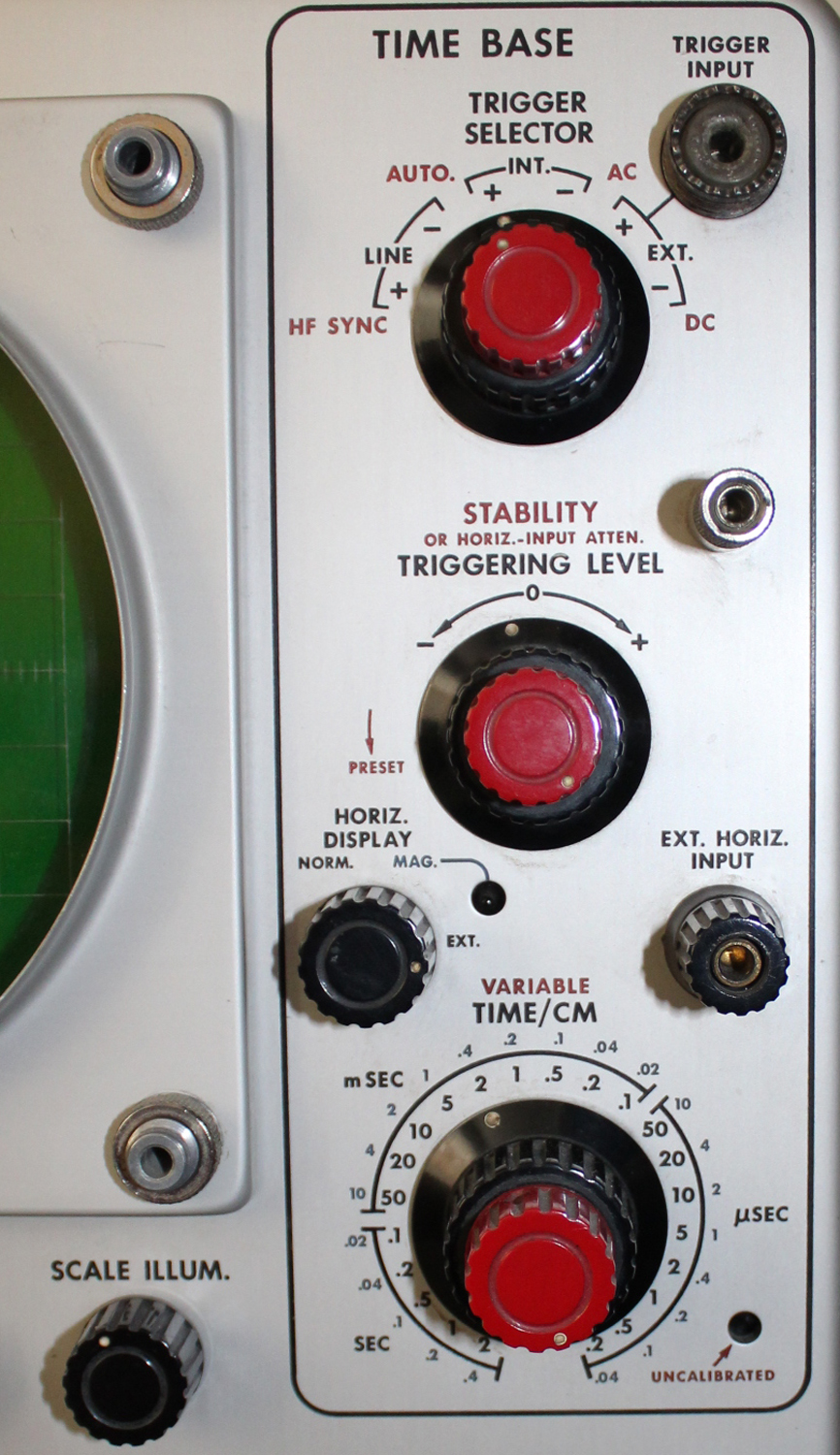
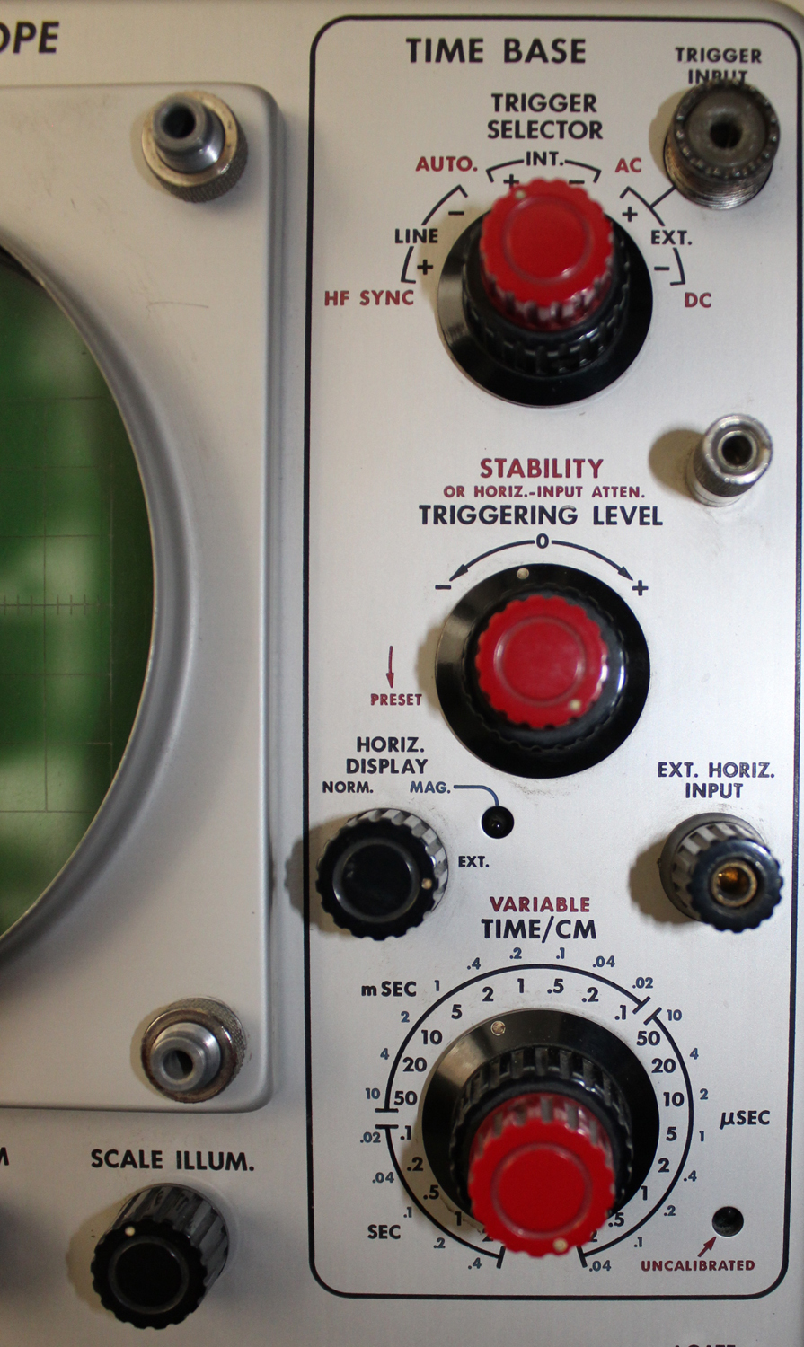
TRIGGER SELECTOR (red knob)       Four-position switch to select four kinds of triggering: H F SYNC- AUTO, AC and DC.(red knob)
TRIGGER SELECTOR (black knob)      Six—position switch to select the source and polarity of the triggering signal.
TRIGGER INPUT                  Coax connector to triggering circuits.

STABILITY                            Control to adjust time-base circuits for  triggered or recurrent operation. This control has a  PRESET position suitable for most triggering applications (S/N 1001-up). This control also function as an attenuator for external signals connected to the EXT. HORIZ. INPUT binding post.
TRIGGERING LEVEL          Control to select the point on the triggering waveform where the time base begins.
HORIZ. DISPLAY                Three-position switch to increase the sweep rate five times in the

MAG. position and to connect the horizontal amplifier to the EXT.
HORIZ. INPUT binding post in the EXT. position. When this control is in the MAG. position, the MAG. light indicates that the sweep rate has been increased five times.

EXT. HORIZ. INPUT    Binding post to apply an external signal to the horizontal amplifier.
TIME/CM                    Twenty-two-position switch to select calibrated sweep rates from 2 sec/cm to .2 μsec/cm.
VARIABLE (red knob)    Continuously variable control to vary the sweep rate between ranges
and to 5 sec/cm. When this control is away from the clockwise
stop the UNCALIBRATE-JD light indicates that the time base is not calibrated.
Vertical Amplifier
INPUT 1 – INPUT 2            Separate signal inputs to the vertical amplifier by way of the INPUT
SELECTOR switch.
INPUT SELECTOR           Four—position switch to select either input connector and insert or remove a dc blocking capacitor from the input circuits.

DC BAL.                       Screwdriver control to balance the amplifier circuits so that there is no shift in the trace position as the VARIABLE control is rotated.
VOLTS/CM                  Nine-position switch to select the desired deflection sensitivity.
VARIABLE                   Continuously variable control to vary the sensitivity between ranges and to 50 volts/cm. When this control is away from the clockwise stop the UNCALIBRATED light indicates that the amplifier is not calibrated.

Auxiliary Functions
+GATE                              Binding post to supply a positive pulse for the duration of the time base.

SAWTOOTH OUT            Binding post to supply a positive-going sawtooth, synchronized with the internal time base.
SQUARE-WAVE CALIBRATOR  Twelve-position switch to select one of eleven taps on a precision voltage divider in the calibrator circuit and to turn the calibrator off.
CAL. OUT                             Coax connector from the calibrator.

POWER                               On-off switch in the lead to the power transformer and fan.
Rear Panel
CRT CATHODE                  Binding post to the crt cathode for the application of intensity modulation.
TRIGGERING INSTRUCTIONS
General
The function of the trigger circuit is to derive from the incoming waveform a sharp pulse of suitable amplitude to trigger the time-base generator. One such pulse occurs for each cycle of the incoming waveform. This pulse is independent of the incoming waveform in shape and amplitude.
The time-base generator develops the sawtooth waveform necessary to provide a linear time base. If the STABILITY control is set for triggered operation, the time base circuits wait until a trigger pulse is received, at which time one sawtooth waveform is produced. After the sawtooth waveform is completed the time base circuits wait for the next trigger pulse and the process is repeated.

The following paragraphs describe the function of the controls which affect this operation.
Later paragraphs describe specific triggering procedures
Triggering Controls
Triggering level
In the Type 515/515A the TRIGGERING LEVEL
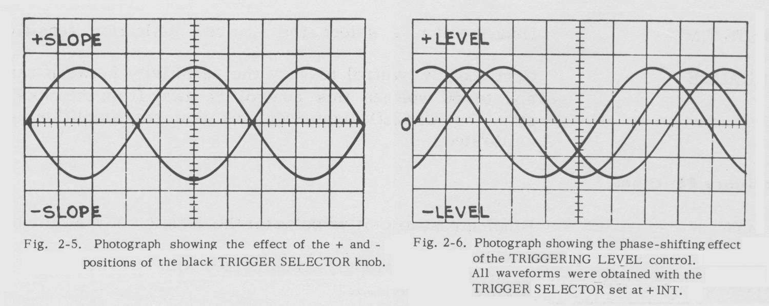
control determines the point on the triggering waveform at which triggering will occur. The TRIGGERING LEVEL control is not a trigger amplitude or gain control if you are accustomed to this type of circuit. Instead, it is an amplitude or voltage discriminator. If the waveform you are observing is centered on the screen and the TRIGGERING LEVEL control is set near 0 the sweep will start as the waveform passes through the center line on the screen. As the LEVEL control is turned clockwise, the triggering point will move above the center line on the screen, and, as it is turned counterclockwise the triggering point will move below the center line. If the LEVEL control is set for a voltage greater than that of the waveform being observed the sweep will stop. Thus, if the waveform is of low amplitude the LEVEL control should be set near 0 (or near the dc level with DC triggering). The LEVEL control is used only in the AC and DC positions of the TRIGGER SELECTOR switch.
Trigger Slope
The black TRIGGER SELECTOR knob selects the trigger source and determines whether the sweep will start as the waveform is going positive or negative. The + positions of this switch cause triggering to occur during the rising portion of the waveform. The – positions cause triggering to occur during the falling portion of the waveform. The trigger slope feature is not used in the H F SYNC mode.
Triggering Mode
The red TRIGGER SELECTOR knob selects the kind, or mode, of triggering used. The DC position will permit triggering on all signals from dc to about five megacycles. It is especially useful for signals below 60 cycles where the sensitivity of AC triggering begins to fall off.
In the AC position, the switch inserts a capacitor in the trigger circuits to make the trigger settings independent of the vertical position of the trace. This mode is slightly more sensitive than the DC mode.
The AUTO position arranges the circuits for an automatic synchronizing action rather than a strict triggering action. In this position the trigger-shaper multivibrator free-runs at
a repetition rate of about 50 cycles. The multivibrator will lock in and run synchronously with trigger signals from 60 cycles to about 2 megacycles. If the trigger signal is lost
the sweep will not stop but will continue at a reduced repetition rate without synchronization.
In the H F SYNC position the trigger-shaper circuits are bypassed and the triggering waveform is used to synchronize the time base circuits directly. The time-base generator must be free-running for this type of operation.
It free-runs at advanced settings of the STABILITY control. This mode of operation is primarily useful for signals in excess of two megacycles.»
§§§
Il testo prosegue nella terza parte.
Per consultare le altre schede dedicate a questo oscilloscopio scrivere: “515A” su Cerca.
Foto di Claudio Profumieri, elaborazioni, ricerche e testo a cura di Fabio Panfili.
Per ingrandire le immagini cliccare su di esse col tasto destro del mouse e scegliere tra le opzioni.